This thread has been locked.

If you have a related question, please click the "Ask a related question" button in the top right corner. The newly created question will be automatically linked to this question.

LMH6554: Frequency response for different input capacitances

Part Number: LMH6554
Other Parts Discussed in Thread: TINA-TI

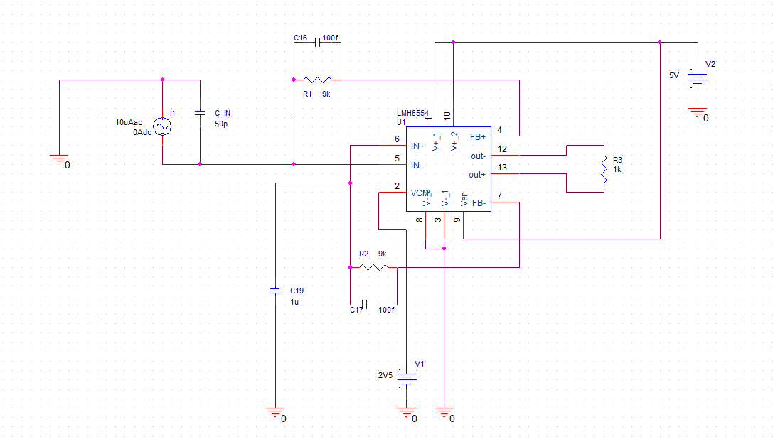
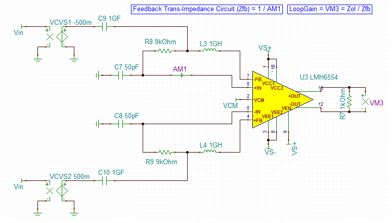
I'm using the LMH6554 as a transimpedance amplifier. The input current source has a capacitance C_IN in parallel. With this setup a PSPICE AC analysis results in the following bandwidths:

C_IN = 1 pF  => BW = 49 MHz

C_IN = 50 pF  => BW = 63 MHz

Usually transimpedance amplifier bandwidth decreases with increasing capacitances at input. What is the reason for this behaviour?

  • Hi Benjamin,

    I guess the 50pF input capacitance erodes the phase margin and causes a peak in the frequency response.

    Can you show the frequency responses of your simulation?

    Kai
  • This is the frequency response for 1pF input capacitance (magnitude = green, phase = red):

    This is the frequency response for 50pF input capacitance (magnitude = green, phase = red):

    The 1pF response appears to be dampened, as if using an excessively high feedback capacitance in parallel to the feedback resistance. However, lowering the feedback capacitance has no effect.

  • Hi Benjamin,

    Here is a link to TI's training series on amplifier bandwidth, stability, fully differential amplifiers, and current feedback amplifiers for background training.ti.com/ti-precision-labs-op-amps-bandwidth-1. Those four categories all play a role, and these videos will give you a more indepth understanding than I can.

    However, when I simulated your circuit in TINA-TI, with a 1pF capacitor, the bandwidth is 72MHz, but with 50pF it is 34MHz.

    Best regards,

    Sean

    CFBDiffAmpBode.TSC

  • Hi Benjamin,

    The reason as to why the 1pF response appears to be more damped compared to the 50pF response is because the former exhibits less phase shift (or more phase margin) compared to the latter.

    To understand this, you need to plot the loop gain and phase expression for each of the scenarios. The loop gain and phase curves can be plotted for the LMH6554 using the below circuit, where VM3 gives the loop gain expression. As you can see, the phase margin for 1pF is 91.61' indicating an over-damped system compared to the phase margin of 70.93'.

    It is important to note that the LMH6554 is a current-feedback topology where the loop gain expression is given by the ratio of open loop transimpedance gain (Zol) and feedback transimpedance (Zfb). For a better understanding of these terms in a current-feedback amplifier, I would recommend you to read this app-note which explains the loop gain expression in detail.

    Best Regards,

    Rohit

    TINA-TI simulation circuit attached. LMH6554_TIA.TSC