This thread has been locked.

If you have a related question, please click the "Ask a related question" button in the top right corner. The newly created question will be automatically linked to this question.

Are Rail to Rail input op amps really Rail to Rail - recommendations

Other Parts Discussed in Thread: OPA333, OPA350, OPA340, OPA365, OPA330

Hi there,


I am trying to choose an single supply opamp for a new design that will be measuring the voltage of a sensor in the rage of 0 - 20mV.  I want to simply filter and amplify this signal using a precision op amp and then use an ADC for measurement.  


I am wondering about the results I will get using an input so close to the negative rail.  When an op amp states that it operates rail to rail on the input, does it really?  I don't see any specs on this topic in the datasheet.  Does the op amp act linear this close to the lower rail?  


What recommendation would you have for topology and op amp to get a linear output with input of 0-20mV?  I will likely be using a voltage reference for the ADC in the 2 volt range.


TIA

  • MJ,

    Common-mode rejection ratio is the spec that covers the topic of linearity of the input stage and its conditions guarantee the performance close to the rail (see below).


    Some of the rail-to-rail CMOS op amps are truly rail-to-rail but ONLY on the INPUT side - the input common-mode voltage range may include both rails.  Actually, some of them can go hundreds of mV beyond the rail and maintain very high CMRR (OPA365, OPA333, OPA340, OPA350).  This is possible with the use of two complementary input pairs or charge-pump at the op amp front end.

    However, no linear op amp can be truly rail-to-rail at the OUTPUT because there is some minimum voltage needed for common-drain (or common-collector) output stage configuration between the drain and source for CMOS (or emitter and collector for bipolar) - saturation voltage - in order for the output transistors to conduct its minimum quiescent current.

    Having said that, some of the CMOS op amps like the ones mentioned above can still swing within tens of mV or better from either rail (see below) but NEVER reach the rail.


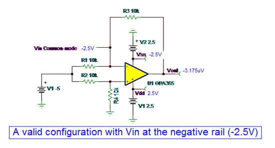
    Thus, since no linear op amp output can ever completely reach the rail, a designer should never place the single supply op amp in a follower configuration with the input grounded (see below);  under such condition, the input stage may be able to maintain high linearity but the output stage is totally saturated.  In such case, the output voltage does NOT represent an input offset voltage but rather a best output swing to the rail (see diagram below) and the op amp does not respond to any small input signal.


  • Thank you for the very helpful and comprehensive response!

  • Just a follow on question, if you dont mind.  I think I will use dual  OPA330 low Vos amp to condition and amplify a 0-20mV signal to be measured by an 10 bit ADC with Vref @ 2.048 V.  I have a couple of questions regarding best connection for the circuit.

    I will be filtering at very low frequency, max 5-10hz and want to suppress as much HF noise as possible. 

    I want maximum dynamic range, so will not be relying on measurements below 1mV due to limiting swing of the output of the opamp.  So I will set the gain to 2.048V/20mV = 102.4.  This will give me valid measurements from input of 1mV-20mV.

    Questions:

    1. Is it ok the output of gain stage 2 directly to the ADC?  It is generally recommended to put a decent sized cap on the input of the ADC, however I dont want to capacitively load the opamp causing instability?  What would you recommend for circuitry between the output of stage2 to the ADC?

    2. Should I use both opamp amps to gain the signal, or just use 1.  In this application I am not worried about bandwidth, so i cold get away with one easily.  What are pros cons to using multiple stages for gain, aside from signal bandwidth and component error cascading?  I could get at least 1 more low pass filter on the input buffer amp if I dont use it for gain.

    3. Would you recommend using any other low pass filtering techniques, topologies.  I think butterworth is probably what I am after here from a precision setup?


    opamp circuit I have so far:


  • MJ,

    Below please find the answers to your question:

    1. Is it ok the output of gain stage 2 directly to the ADC?  It is generally recommended to put a decent sized cap on the input of the ADC, however I dont want to capacitively load the opamp causing instability?  What would you recommend for circuitry between the output of stage2 to the ADC?

    Typically you do not want to directly drive the ADS because of the ADS charge injection from sample and hold to which op amp may not be able to respond fast enough.  For that reason, it is typically recommended  to place RC filter in front of ADS (see attached presentation for details).  Having said that, some op amps like OPA350 is able to drive directly large capacitors in the range of tens of uF.


    2. Should I use both opamp amps to gain the signal, or just use 1.  In this application I am not worried about bandwidth, so i cold get away with one easily.  What are pros cons to using multiple stages for gain, aside from signal bandwidth and component error cascading?  I could get at least 1 more low pass filter on the input buffer amp if I dont use it for gain.

    The higher the close loop gain of the op amp, the longer settling time, thus this all depends what is the sampling rate of the ADS.


    3. Would you recommend using any other low pass filtering techniques, topologies.  I think butterworth is probably what I am after here from a precision setup?

    See attached presentation on driving SAR ADCs.

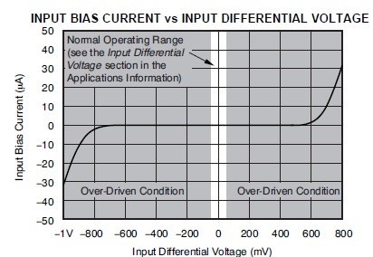
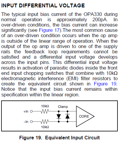
    A word of caution: you need to be careful not to over-drive the OPA333 output beyond its linear regionAllowing this will cause a loss of a virtual short between the input terminals which in turn will result in a dramatic increase of the input bias current, IB (see below for details).  A large increase in IB (tens of uA) may cause a lock-up condition when used with the large input resistors.


    a2d_in_few_steps_final.ppt
  • Hi Marek,

    Thank you very much for informing me of these pitfalls. I have been doing some further reading, including you attached notes, very nice!   It looks like I may want to reconsider op amps to use in this design based on the capacative loading requirement and the need to stay as close the bottom rail as possible.

    Just to verify that I understood your warning about driving the opamp outside of its linear region.  I believe you are referring to the my connection of the senor output voltage (0-20mV) directly to the non-inverting input, which when the output voltages are very low would cause the opamp output to drive toward the lower rail fall outside of its "linear region"?  By driving this closely to the rail, IB and differential input voltages will cause significant error in measurement?  Were you referring to more than this?

    Question 4:  It appears that I need to add an DC biasing offset to the sensor voltage in order to ensure that the opamp output stays within range.  Would you recommend using an summing stage that sums the sensor voltage and a sufficient dc bias to keep the sensor gain stage within the opamp linear region.  Is there another means of dealing with this?

    In taking another look at these issues and looking at the opa340, op350, I see that they may be better fitting in in that they are capable of driving capacitive loads and the output swing much closer to the rails, but at the expense of a much higher Vos, 8uV vs 150uV typical.  It seems that I am looking into  balance between accuracy of measurement(varying Vos between opamps) and dynamic range (linear range of the opamp outputs) due to differing linear regions of operation between the amps.  Is this about right?

    amp:   330 340 350

    Vos

    8/50uv 150/500uv 150/500uv

    out range from rail

    30/100mv 1/5mV 1/50mV


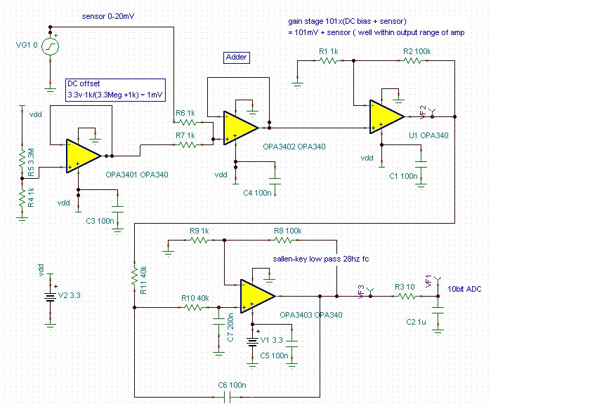
    Here is stab  at addressing the issues.  Any suggestions?