Because of the Thanksgiving holiday in the U.S., TI E2E™ design support forum responses may be delayed from November 25 through December 2. Thank you for your patience.

This thread has been locked.

If you have a related question, please click the "Ask a related question" button in the top right corner. The newly created question will be automatically linked to this question.

OPA615: Fast Pulse positive detector using OPA615

Part Number: OPA615
Other Parts Discussed in Thread: DEM-OPA-MSOP-1A, TINA-TI, DEM-OPA-SO-1C

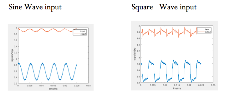
I am trying to build the positive peak detector listed as figure 48 in the datasheet . I used the evaluation board and it did not work and I am wondering if someone has actually built this and has tried to see if it can detect the positive peak and hold it. Also the packaging of OP615 does not come with pin configuration. I have already used two boards and still did not get anything. I shifted my circuit to a breadboard but it seems my output is just following the input and there is no holding that is occurring even when I use the 27 pf capacitor.  Below are my outputs for two trial waves (square/sine). Also is there anyone who can help me with how I can wire the evaluation board correctly for the fast pulse detector because there is no directions of how it is wired and its kind of confusing just looking at the data sheet of the evaluation board because it only gives pins.
  • Hi Orwell and welcome to E2E,

    What type of diode are you using and what is the desired hold time? I recommend building a working circuit in TINA-TI before you spend the time and money to put it together on a PCB.  Look at page 3 of the OPA615 datasheet for the pinout that is referenced in the evaluation board. Are you using DEM-OPA-MSOP-1A? It's not a perfect fit, but you could cut the trace between pin 3 and the hold capacitor and solder in a shottky diode, possibly needing to use thin wires.

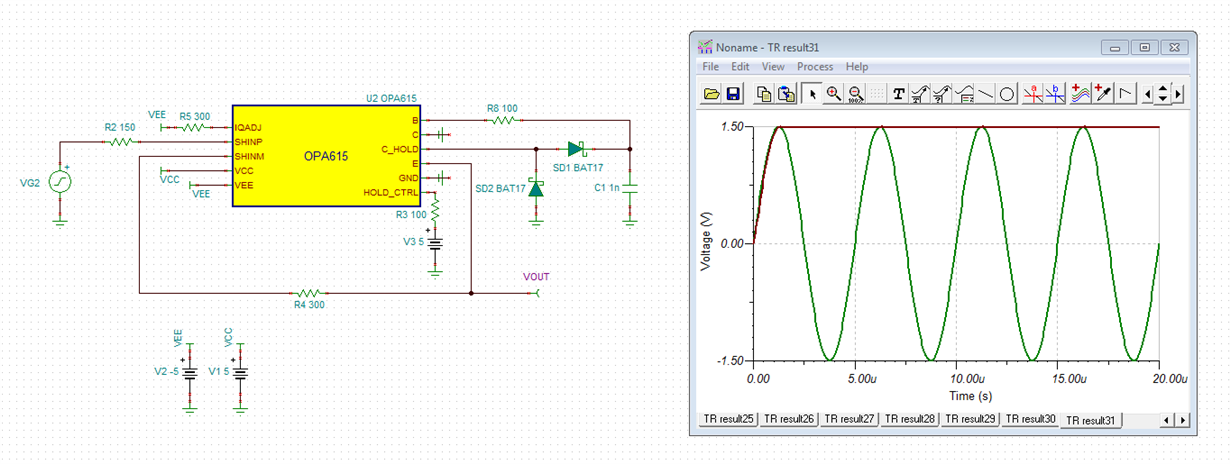
    Here is a simulation to get you started. 2337.OPA615PeakDetector.TSC

    Best regards,

    Sean

  • I am using the schematic suggested in the datasheet - figure 48. The circuit has been used before in some published paper so I am not worried about whether it works. The board I am using is the DEM-OPA-SO-1C and I have already tried two boards and two OPA515s and I havent gotten any output. When I shifted to the breadboard the output is there but as you can see, it seems it is just sampling and following the input and there is no holding occuring at all

  • Hi Orwell,

    try this circuit:

    orwell.TSC

    You might also want to have a look into this thread:

    e2e.ti.com/.../718099

    Kai

  • Thanks, I am trying the circuit but can you tell me what pins are SHINP and SHINM on the OPA615

  • Hi Orwell,

    "SHINP" and "SHINM" stands for "S/H input +" and "S/H input -". These are the pins 10 and 11, according to figure 48 of datasheet.

    Kai
  • Hi Orwell,

    Did this resolve your issue?

    Best regards,

    Sean
  • Hello , I am kind of having an output that resembles what I want but I do not understand why it has so much ripple and also I cannot account for the DC offset shown in the graphs below. Can you help me in seeing how I can navigate this.

    Sometimes the circuit rings like the latter graph shows I do not know what the problem is , and also the dc offset is changing with frequency for this given circuit so how can I navigate that

  • Is it possibly because the capacitor doesn't have enough time to decay with a sine wave input? As in Kai's simulation? That might account for the large offset. Maybe try a lower frequency square wave with a low duty cycle.
  • Hi Orwell,

    the OPA615 is a very fast chip and you need to use HF techniques to make it work properly. Breadboarding will not give good results.

    Another issue is the cabling. For the input signal you should use a 50R driver, a 50R cable and a 50R termination resistor at the input of OPA615. The same is valid for the output. Here also 50R technique should be used. Mount a 50R series termination resistor directly at the output of OPA615 and connect the output signal via a 50R cable to a 50R scope input. Figures 45, 47 and 48 of datasheet show what I mean.

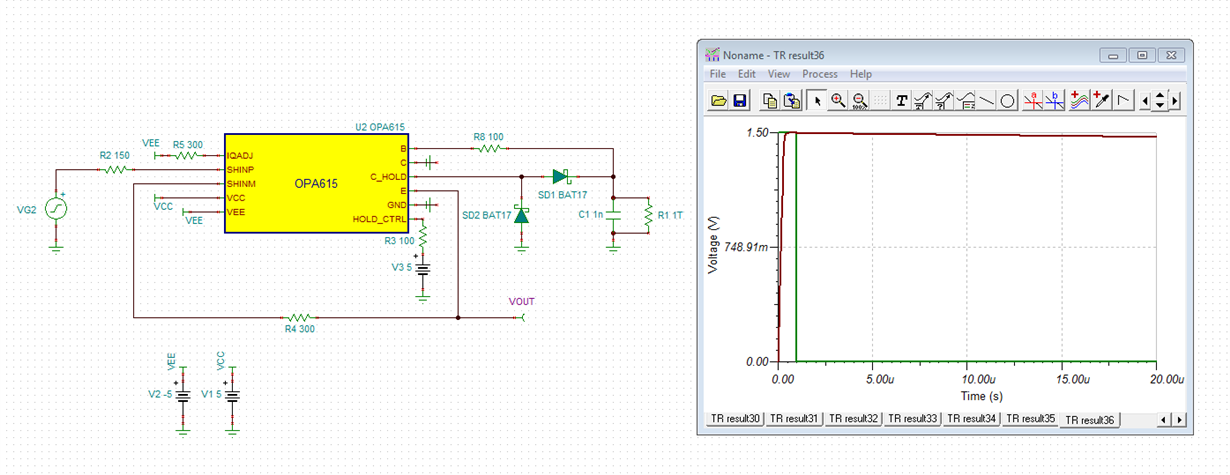
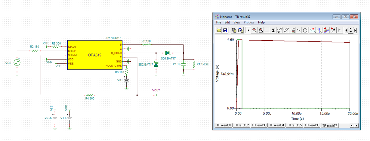
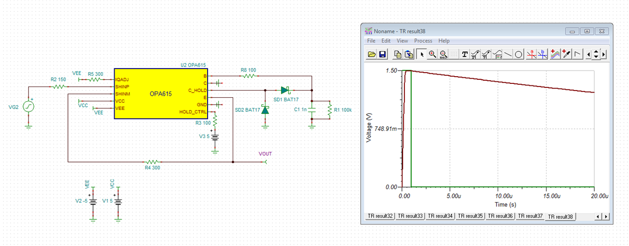
    Referring to what Sean mentioned: To make the output signal decay faster, a resistance can be mounted in parallel to C1:

    Kai