This thread has been locked.

If you have a related question, please click the "Ask a related question" button in the top right corner. The newly created question will be automatically linked to this question.

INA219: Data Hold Time in Standard Mode

Part Number: INA219
Other Parts Discussed in Thread: INA3221

Hi Team,

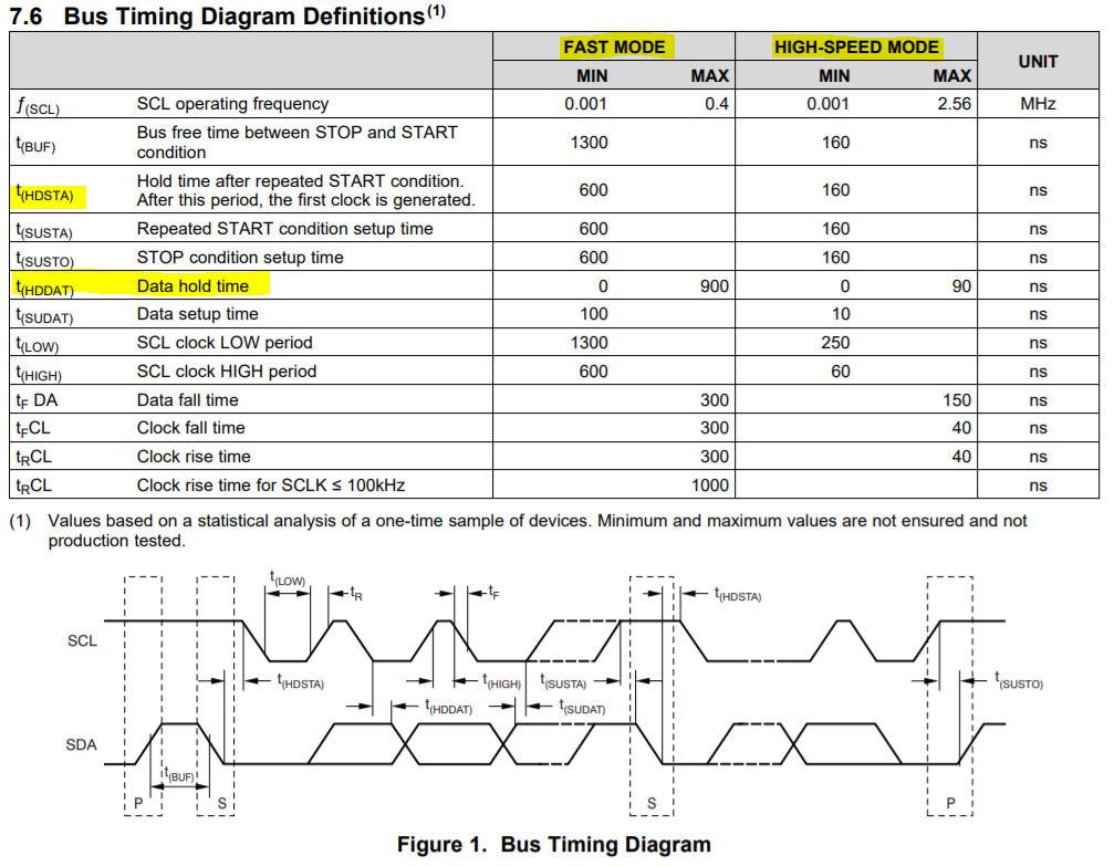
Could you please provide the Data Hold Time information (t(HDSTA) & t(HDDAT)) in Standard Mode (100 kbps)? Thanks!

The datasheet lists the information in Fast and High-Speed Modes only.   

Best regards,

Sam Ting

  • Hello Sam,

    Thanks for using the forum. The bus timing specifications provided for fast mode also apply to standard mode.
  • Hey Sam,

    Are they observing this behavior during a read or a write operation? The table we have in the datasheet actually combines both operating conditions, when in reality they should be separated. If it is a write operation, the min specification is the critical bound that must be met, while for a read operation the max is the critical bound that must be observed. If your customer is observing a Data Hold Time greater than 900ns, its possible that there pullup resistance is too larger, or their trace capacitance is also really large. Can you supply a oscilloscope shot of there I2C communication?
  • Hi Patrick,

    What’s the concern from customer is the max Data Hold Time in Standard Mode. In this mode (100K Hz), the clock frequency is much slower than Fast Mode (400K Hz) so the half cycle is 5us. We think the data is still valid for Master as long as the data hold time is less than 5us and we don’t understand why the data hold time should be limited less than 900ns for standard mode. Is there any risks if the timing greater than 900ns? Could you please comment on this? Thanks!
    By the way, we notice it has no max limitation in similar part, INA3221.

    Best regards,
    Sam Ting
  • Hello Sam,

    I originally got the details wrong on the operation of this part.  Sorry for that.  The following is what one of our design engineers told me with regard to the specifications of this part.  Firstly, the specs we have adhere to those defined by philips (now NXP) for the I2C protocol.  To see those specs you can go here, page 48.  According to those specifications, you can determine what the max tHDDAT should be based off of the tSUDAT, trise, tfall, and thigh times.  Lets use your 100KHz and assume that your clock and data lines have rise times of 1000ns and a fall times of 300ns.  We will also assume your time period where the clock is high is 4 us.  With a 100KHz clock, your clock period is 10us.  If we evaluate one period of the clock, we can determine the remaining time that corresponds to what tHDDAT must be so that the slave and master devices can communicate.  In this case we have Period -data transition time (max) -data setup time- clock rise time- clock high time - clock fall time =10us-1000ns-250ns-1000ns-4us-300ns=3.45us.  If your rise and fall times are shorter or your frequency is smaller, this hold time can be longer.  If your hold time exceeds whatever you calculate for the conditions you impose with your clock and pull-up resistances, you may have communication errors as the data and clock will no longer be operating on the same frequency.