This thread has been locked.

If you have a related question, please click the "Ask a related question" button in the top right corner. The newly created question will be automatically linked to this question.

LMP7721: Question.

Part Number: LMP7721
Other Parts Discussed in Thread: LM35, ADS1115

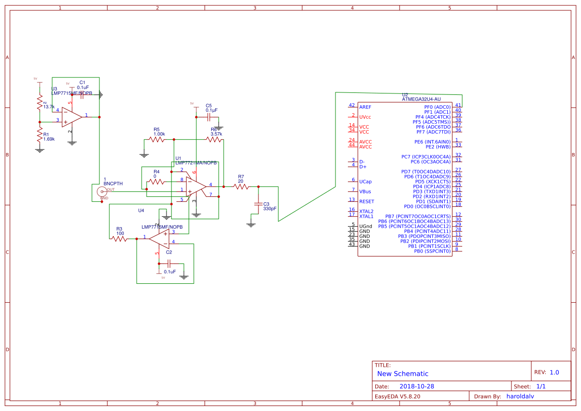
Hello, On EasyEDA software I have BNC connector with Output and GND pads, on sample I see "pH Bias", Does this go on BNC Connector GND pad. Kinda confused since I see other circuits with nothing on GND. Thanks.

  • Hi Harold,

    Please provide a circuit schematic of your application.

  • Hello, I'm having issues posting png file, here is the link to EasyEDA I had no time so it's a bit messy :P but hopefully I'm understanding how the LMP7721 works.

  • Hello Harold,

    You have to click "Insert Code, Attach Files and more..." in the lower right. This brings up the HTML format editor.  Then click the "Insert Media" icon (square with a plus icon - to the left of the paper clip icon).


    As I pointed out in another LMP7721 thread, you do not really need the guard buffer (U4) if you are just guarding locally around the input pins and not driving large guard areas or cable shields.

    You can just connect the "guard" trace to the negative input. Your impedance is low enough at that point (<1k) that the extra capacitance should not cause any  peaking.

    You should also have a current-limiting resistor, say 100-470 ohms, in series with the output of the bias driver U3 in case the output gets shorted (similar to U4 output). Anything that goes off-board should be protected from accidents...

    How stable is your 5V supply? The PH sensor only puts out ±400mV - so any variation in the bias voltage will appear in series with your sensor, causing it to "wander" with the supply. You may want to consider using a reference (ideally the internal ADC reference if you can get at it). I would recommend using one of the ADC channels to monitor the bias voltage to keep an eye on it...

  • Hello  Paul,

    I will be using LiPo battery 3.3v with boost 5.25V.  Do I trace Guard to Pin 8. I went with ADS1115 for converter, I will also be adding a LM35 later, Let me know if i'm doing this correctly, Thanks.

  • Hi Harold,

    Looks okay.

    You need to connect the guard to pin 8. The "guard" pins 2 and 7 are not connected to anything internally, so your guard is unconnected as shown above.

    Keep in mind that you are using the supply as a reference, so any changes/drift/transients on the 5V supply will appear in your readings. I would also monitor the reference drive voltage (U3 Pin1) with an extra ADC channel.

    Also make sure the switcher supply is well filtered and keep the inductors away from the low current circuitry.