This thread has been locked.

If you have a related question, please click the "Ask a related question" button in the top right corner. The newly created question will be automatically linked to this question.

LMV324: application problem

Part Number: LMV324
Other Parts Discussed in Thread: LM324

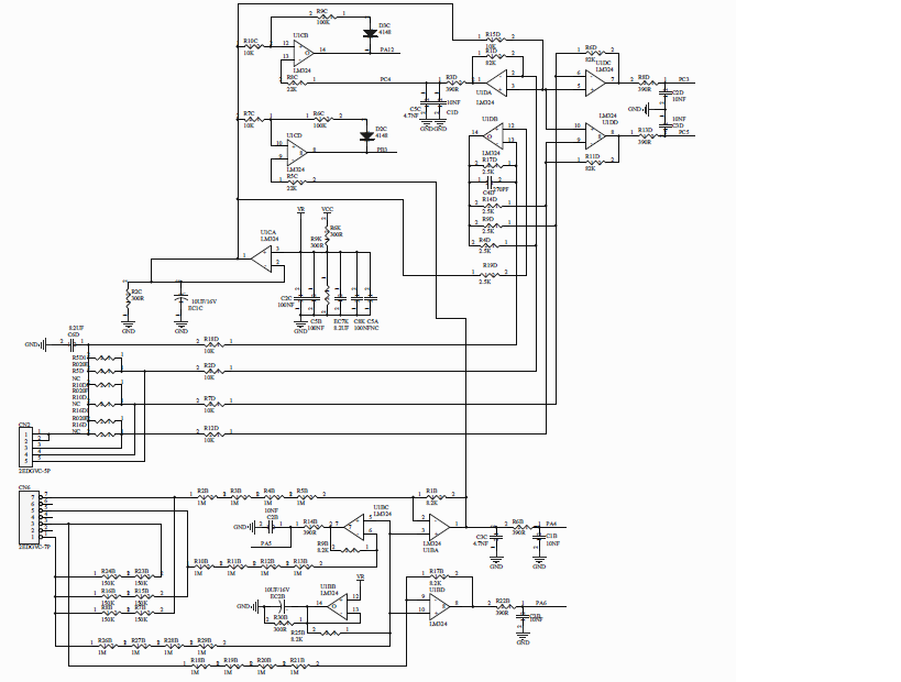
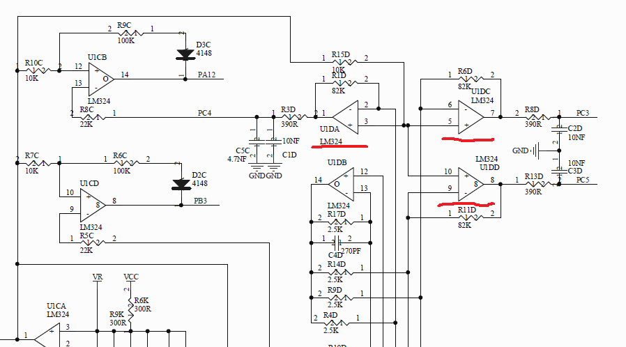
The circuit diagram is as follows. The problem of U1D is that the three channels, U1DA, U1DC and U1DD, have consistent input signals but inconsistent output signals.Do you have any Suggestions?

  • Hi User,

    Can you provide some further information on what the desired output signals should be and what the incorrect/inconsistent signals are? Scope shots would be good, but we definitely need more detail.

    -Paul
  • Hi Paul:
    The input of the amplifier is to collect the induced current, and then the resistance is sampled, and then output to the ADC that is embedded in the MCU.
    What happens now is that good boards have input and output of about 1.65v, while abnormal boards have input of about 1.65v and output of about 1.74v.About 10 boards, 3 boards will have this anomaly.
    I used to use the 324 chip of ST. As it is P2P, I directly replaced it with LMV324.
    I replaced the abnormal board with the chip of ST, and the input and output were about 1.65v again.
    Now I want to use TI's chip, what should I do?Any Suggestions?
  • Hi,

    maybe the LMV324 is more vulnerable to high load capacitances? U1CA sees 10µF at its output? That's quite a lot and can erode the phase margin:

    Your supply voltage is 3.3V?

    lmv324.TSC

    Kai

  • My stability analysis shows that you likely have enough phase margin with your isolation resistor. I used a preliminary model which is more accurate for Aol and Zo across frequency and show that you have around 65 degrees of phase margin.

    Are you able to take bench data with an oscilloscope so that we can see the abnormal output signal?

    It looks like the circuits you highlighted have a gain of -82k/10k = -8.2. Am I understanding that correctly? What is the voltage developed across the current sense resistor?

    -Paul
  • User,

    Has this issue been resolved? If yes, please mark the thread as resolved.
    If you need more assistance, provide the measurements that Paul suggested.
  • The gain is 8.2. This problem exists with the device. I bought the device elsewhere.I plan to apply for samples on the official website and try again
  • Hi,

    divide and conquer: Remove one cap after the other which you have connected directly at the output of LM324 and see what happens.

    Kai