Dear colleague,
In our http://www.ti.com/lit/ug/slau508/slau508.pdf,


Customer asked me:
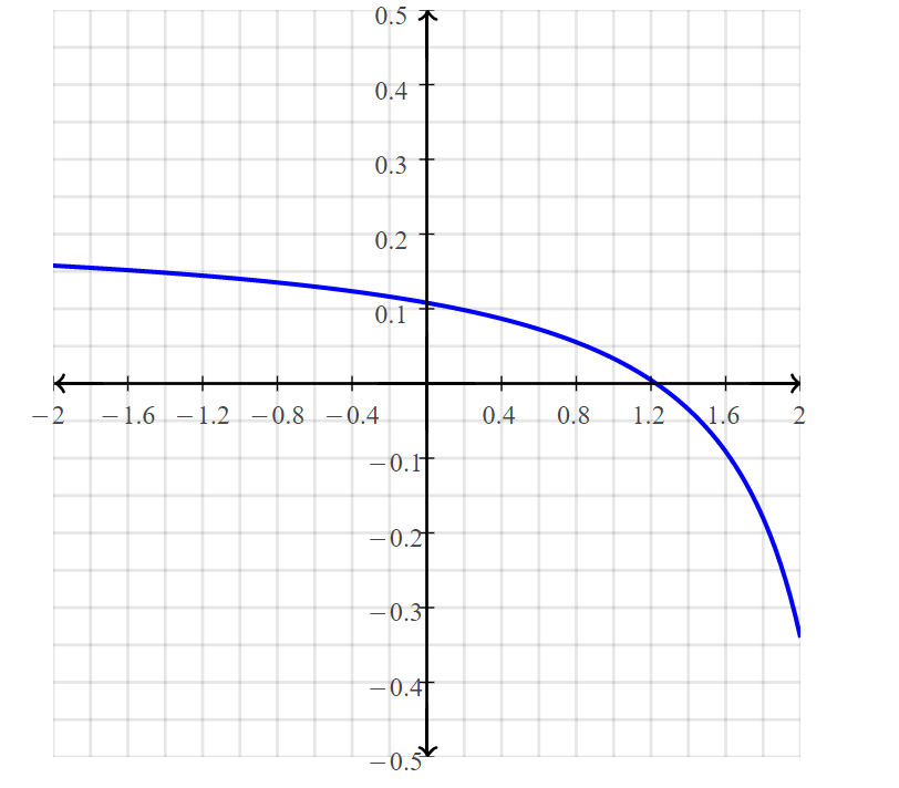
1. Why output error is larger when input voltage is in 1.3V-2V?
2. For slowing down the output error, how should we do ?
Best Regard,
Rock Su
Dear colleague,
In our http://www.ti.com/lit/ug/slau508/slau508.pdf,
Customer asked me:
1. Why output error is larger when input voltage is in 1.3V-2V?
2. For slowing down the output error, how should we do ?
Best Regard,
Rock Su