Because of the holidays, TI E2E™ design support forum responses will be delayed from Dec. 25 through Jan. 2. Thank you for your patience.

This thread has been locked.

If you have a related question, please click the "Ask a related question" button in the top right corner. The newly created question will be automatically linked to this question.

OPA549: thermal shutdown of one amplifier controlling multiple other amplifiers

Part Number: OPA549

HI, 

we have an application where we have one main OPA549 in an inverting gain configuration (ie. ~30x), and one or more OPA549's in 1x gain configuration as followers.  The follower OPA549 outputs are connected in parallel with main OPA549 per the datasheet recommendation with 0.1 Ohm series ballasting resistors for even current sharing among amps.  This all works fine, except we notice for example if one OPA549's goes into thermal shutdown, only it shuts down individually, it has no direct way to communicate it's thermal shutdown with the other amplifiers to shut them off as well.  This happens sometimes when our overall amplifier network is initially powering some particularly nasty reactive loads, where we want the system to cough and ride-through the start up transient.  In the configuration where we have one main amp and one follower amp, we can have the situation where the main amp coughs (thermal shutdown) yet the follower stays enabled.  Some loads are so nasty that the load itself is the secondary of another transformer accidentally connected that is powered from the AC line!  We want our amplifier to survive all kinds of abuse.  In the lab we've never been able to blow up an amplifier with any torture test, yet in the field, when we occasionally have an OPA549 blow up, it is always the follower blown out, not the main.  The heat sinking/air flow is identical for both follower and main and we want to keep it that way.

Currently our circuit has global OPA549 enable/disable capability via computer control, as well as computer monitoring which gets flagged if any OPA549 is in thermal shutdown.  So we currently have the capability to shut down all OPA549s together if anybody is in thermal shutdown, via software.  But, we don't want to rely on the computer control since it is slow, on a different board, prone to programming errors/micro freezes, etc.  We want shutdown circuitry which achieves the following:

1) shuts down all OPA549s simultaneously (main+all followers within say 2usec) if anybody is in thermal shutdown.

2) allows all the OPA549s to resume operation together once the thermal shutdown is cleared (typically we see thermal overloads clear within 2msec in cough situations).

3) still allows global shutdown/global enable via a software loop with the understanding that if any amp is in thermal overload, the thermal overload over-rides the software controlled enable.

For 1,2 we want that circuit to be minimal amt. of marginal circuitry per OPA549 follower added to the system, and ideally with no programmable parts such as micro-controllers etc. 

It turns out we have a circuit which should achieve the objectives 1,2,3, but it's a bit involved, using one comparator per OPA549 along with some diodes. 

Now for the question: Is there any other known good way to achieve 1,2,3 in a TI application note or other document?  I was hoping the E/S pins of multiple OPA549's could just be paralleled to achieve this, but I noted from a separate thread (and empirically) that that approach can't work (side note: too bad the E/S pin pull down capability isn't about 5x stronger than the pull-up capability).

Best,

Richard


  • Hi Richard,

    Can you share your OPA549 circuit schematic?

    Regards, Thomas
    Precision Amplifiers Applications Engineering
  • HI Thomas, 

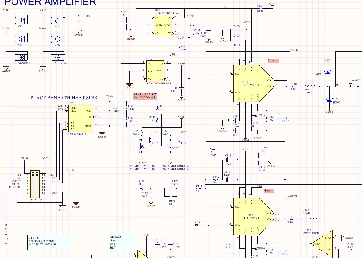
    here's the existing circuit below.  From this schematic snippet the whole control loop won't make sense, but you can see that the 2 OPA549 outputs are combined in a parallel fashion and we have logic (U101, U107) which reads the thermal shutdown status of each amplifier.  If either amp is shut down, we get an L signal on the E/S signal of J102 pin4 (left side of schematic).  We enable both amps via ENABLE (J102 pin6).  The issue is that if the main amp U108 goes into thermal shutdown, nothing shuts down U104 (since the software loop of reading E/S OUT is slow/sometimes non-existent).  Things which can cause U108 to thermal shutdown are nasty accidents on the load, other circuitry connected to J101, such as the load becoming power source or huge 100% reactive load for short period.  In those instances we'd like both amps to shut down in unison and come back up as soon as possible. We definitely don't want the shutdown to become latched, we want both amps to be able to cough in unison and ride through a start-up period of a second or so.  

    For my new circuit which should achieve what I want, I'd rather try it out first before sharing.  It should work but it's more complicated than what I'd like.  I just have to believe somebody else has already solved this problem before.

    Best,

    Richard

  • Hello Richard,

    Nice implementation of the two OPA549 power op amps in the master-slave configuration! I am glad to hear it works well.

    I understand your explanation of how you would like to modify the circuit so that either of the two OPA549 thermal flag active status indications would result in both op amps shutting down during a thermal shutdown of either op amp. If that is achieved, when the one op amp goes into thermal shutdown the other would simply go into the E/S shutdown mode. Once the thermal shutdown condition clears they would both go back into enabled operating mode.

    We have not encountered a request for this OPA549 master-slave circuit function before so I don't have a circuit on hand. However, it certainly does appears feasible that a circuit could be derived that accomplishes the desired function. You have indicated that you have something that you believe will accomplish the task.

    I've drawn out some circuit ideas, but don't have anything that works yet. Additionally, I am not sure what can be done about making the two op amps react closely in time. The thermal shutdown and E/S function can both disable the OPA549 output, but their internal circuitry is quite different resulting in different response times.

    I'll continue to work on this and see if I come up with something not too terribly complex!

    Regards, Thomas

    Precision Amplifiers Applications Engineering

  • Hi Richard,

    I am continuing my efforts to come up with a circuit to shut down the output of both OPA549 op amps should one or the other go into thermal shutdown. I am finding that sharing the E/S pin with the thermal shutdown flag function makes this more difficult to implement than if they were brought out to separate pins.  My first attempt looked good on paper, but failed to behave as hoped when simulation.

    You mentioned, "In the lab we've never been able to blow up an amplifier with any torture test, yet in the field, when we occasionally have an OPA549 blow up, it is always the follower blown out, not the main."

    We have had some internal discussions as to why the follower OPA549 would be the one that becomes damaged and have some ideas why that could happen. Rather than try and explain them in a typed out exchange, a conference call might be a better use of time. If you would like a discuss this, please let me know and we will set something up for next week.

    Regards, Thomas

    Precision Amplifiers Applications Engineering 

  • HI Thomas,

    a call this week would great.  Can you send me your email address?  

    Best,

    Richard

  • Richard

    Since this has been taken off-line I'm going to close the e2e thread

    Thanks
    Dennis