This thread has been locked.

If you have a related question, please click the "Ask a related question" button in the top right corner. The newly created question will be automatically linked to this question.

Unable to get single-supply inverting circuit to work to trigger a BJT

Part Number: NE5532

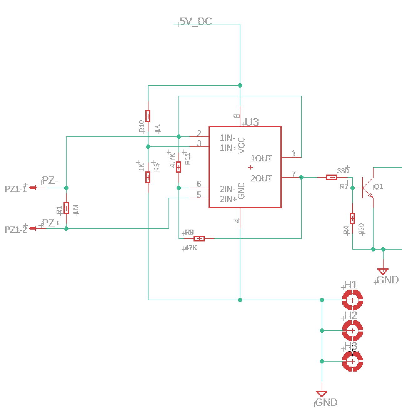
I'm attempting to get a very fast/precise bump sensor built using a piezoelectric disk, NE5532 Amp, a BJT, and an atmega8/2560. In the schematic below, the emitter of the BJT is attached to an interrupt enabled pin on the arduino, which is watching for either a rising edge or falling edge depending on which type of bjt I choose to go with. So far I've been using an NPN.
The intended circuit is supposed to be providing a 2.5v (midrail) bias from the first opamp, which should act as a virtual ground for the second inverting circuit. when the disk is flexed, it's supposed to draw OUT2 low which should effect the BJT and trip my interrupt.

The actual behavior is very different. I'm getting a variance of only about 10mV on Out2. When the piezo is not in the circuit, it peaks at around 0.735V when flexed, so I'm not sure how the gain is coming out lower than expected.

  • Hi Alan,

    Welcome to e2e.
    Have you tried each half of the circuit separately?
    Perhaps you can first try to ensure that the first amp is providing the expected bias. Then check the signal coming from the piezo with R1 and R5 connected. Perhaps R1 in parallel is causing the voltage to drop.

    Best regards,
    -Ivan Salazar
    Applications Engineer - Low Power Audio & Actuators
  • Well I just identified part of my problem. I built this circuit up using a salvaged opamp from an old board cus I didn't have one to test with on hand at the time. When I knocked it out of the board, a small sliver of solder bridged the second amp's in-/in+/out pins. I just cleaned it up and I'm going to test again. I'll update with the behavior of the circuit once I do
  • OK, Update after cleaning the amp and rebuilding the circuit:

    The inverting behavior is different depending if I couple the inverting input to the piezo vs an actual DC voltage.

    Now I'm actually getting the expected 2.5v on out2 with no activity, rather than the ~4.1V I was seeing before, so that's good. When I attach the piezo, and flex it, the voltage actually climbs about 20mV now instead of dropping as I expected, however, if I tap the in2- pin with a +5V wire, Out2 does drop down to ~1.34V. So I'm getting that negative edge behavior I want only from a dc source at the moment.

    Also even when using a higher gain ratio, or a lower DC offset, I just can't get the output pin to go lower than that 1.34V, which isn't low enough to trigger the BJT or microcontroller pins.

    Anyhoo, Amp1 is definitely doing it's job of voltage following, and keeping the In2+ pin at 2.5V, but I think Amp2 is having some issues with how it interacts with the Piezo disk. Maybe not enough current from the piezo?

    I'm going to try a different configuration using Amp1 as a buffer to give it a bit more oomf, and just use a divider on In2+ instead and see if that makes a difference
  • Ok so I'm getting some good results from the buffer, but not the inverting circuit.

    For kicks I set up the BJT on the output for the buffer alone, and was able to get it to trigger that way, but I don't always know exactly what voltage this circuit will be using, and I also don't always know which piezo disks will be used either so I'm still trying to integrate the inverting circuit to address that uncertainty.

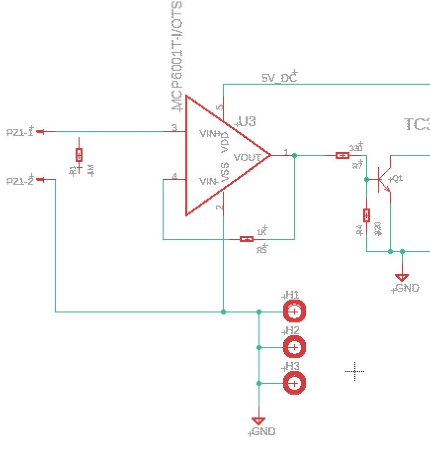
    anyhow, the circuit I built that is able to drive the BJT:

    By adjusting that voltage divider on the BJT's base, I was able to get the amp's output below the trigger threshold of the BJT, and the output is just high enough to trigger properly.

    However, if I attach Out1 back to the amp2 inverting circuit, I get nearly the same problem as before with like ~20mV change on out2

    Edit: to clarify, I'm still using the same IC, I just built the schematic using a different one that's easier to read for a single amp

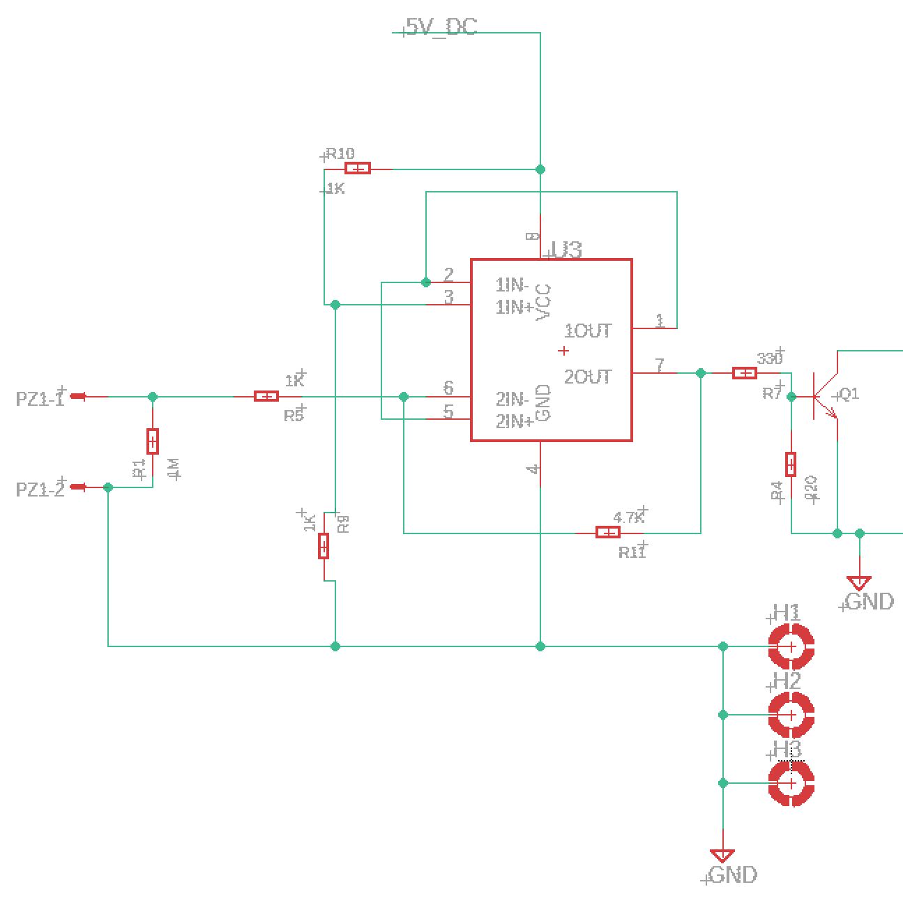
  • OK so I got it working (mostly) after speaking with one of the more experienced electrical engineers in my office, and he steered me in the right direction. I was simply hooking up the reference voltage and Piezo up in the wrong spots.

    Schematic:

    I can draw out a simplified schematic if desired, but basically I wasn't using the "virtual ground" properly and was still attempting to use global ground. Now the circuit works as intended