- Ask a related questionWhat is a related question?A related question is a question created from another question. When the related question is created, it will be automatically linked to the original question.
Hi,
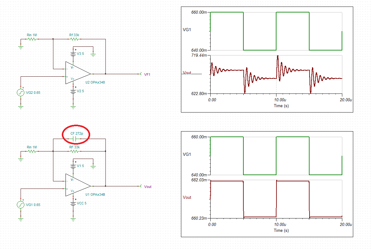
I have a OP340 in non-inverting configuration driving into a TLV2548 ADC. At lower steady state amp input voltages (in the region of 0.65V) I'm see an oscillation at the output of the amp/input to the ADC as shown below, as I increase the input voltage the oscillation will disappear and the circuit will behave as expected. Increasing the values of R1 and R2 (R9 and R42 in my attachment) 10 fold eradicates the noise. I've not been able to replicate this via simulation and am looking for advice as to the cause of the oscillation (value of R9 too low?) or any alternative recommendations to remove the noise. I've also tried an additional low value series R between the amp and ADC to no effect.
Thanks