This thread has been locked.

If you have a related question, please click the "Ask a related question" button in the top right corner. The newly created question will be automatically linked to this question.

LM2904: Unused pin

Part Number: LM2904

Hi team,

  I have a question regarding to the usage of unused pins of LM2904. Let's say i only use one channel and the other in+/in-/out pins are all connected to ground. Does the device consume extra power? If so, how should I deal with the unused pins, keep them floating or others? Thanks.

Regards,

Patrick

  • Hi Patrick,

    I would do it this way:

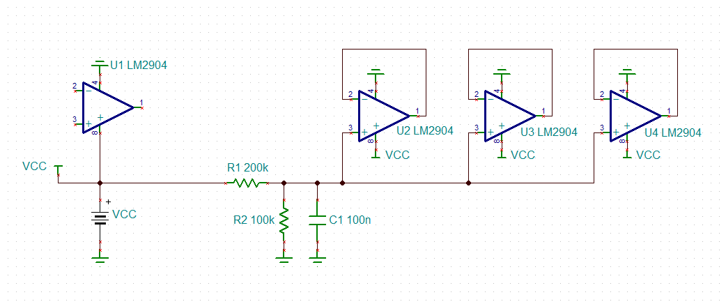
    The voltage divider generates an input voltage for all the unused LM2904 which does not violate the common mode input voltage range and this for all supply voltages >=3V. The unused OPAmps are wired as voltage followers. This allows the outputs of unused LM2904 to swing within their regular output voltage range. By this no extra supply current is drawn.

    The voltage divider is rather high ohmic to keep the additional supply current (through the voltage divider) to a minimum. The 100nF cap across R2 increases the stability by reducing the source impedance at higher frequencies.

    Kai

  • Hi Patrick,

    To add on to what Kai has provided, we have some blogs and documents which cover what to do with an unused op-amp:

    www.ti.com/.../sboa204a.pdf

    e2e.ti.com/.../the-unused-op-amp-what-to-do

    Best,
    Paul
  • Former Member
    0 Former Member

    Hello Patrick,

    We are actually about to put out a big app note which includes a couple pages on unused connections. Since it has yet to be published, I will summarize here below:

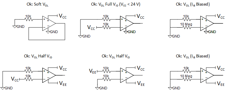
    1. Do not connect inputs directly to GND. If needed, add some resistance to limit any possible, transient input currents to 10 mA at most. Typically this can be done with a 10 kOhm resistor.  Taking this step will help to protect the unused channel from damage.

    2. The best way to handle unused channels is to put them into linear operation mode and ensure the inputs are not directly connected to a low impedance node. This both protects unused channels and avoids interfering with the channels that are being used.

    3. The next best way to connect these devices involves a non-linear configuration.  These may decrease the supply current drawn and save you some power.

    Best Connection Practices:

    Acceptable Connection Practices:

    Regards,

    Daniel

  • Hi Daniel, Paul, Kai,

      Thank you very much for the details. And I look forward to your coming big app note:) 

    Regards,

    Patrick