This thread has been locked.

If you have a related question, please click the "Ask a related question" button in the top right corner. The newly created question will be automatically linked to this question.

OPA1622: Any comments or concerns using OPA1622 to drive balanced headphones

Part Number: OPA1622
Other Parts Discussed in Thread: OPA1632, INA1620

Hi,

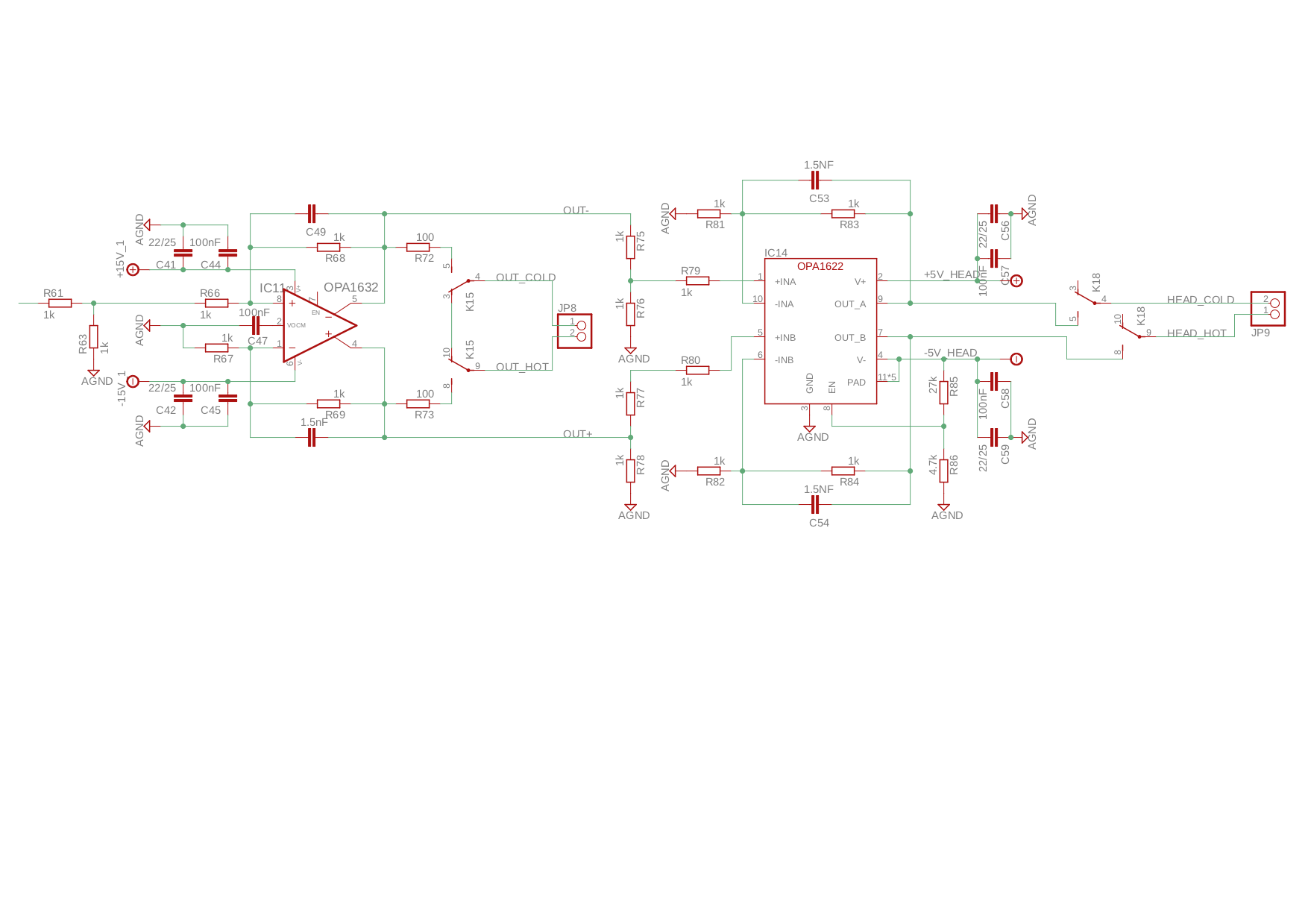
can I use the OPA to drive balanced headphones? Please note my schematic below. Any comments or concerns? 

R75 .. R78 are used to adapt to different headphone impedances. It would be nice to adapt them by using switches. Can you recommend an ultralow harmonic distortion / noise switch?

Many thanks in advance

Andreas Nicklas

  • Hi Andreas,

    Our audio guru is out this week in training. I am not sure if he will be addressing the E2E while away. Please give us a little time to consider your circuit and get back to you in the event that he doesn't.

    Regards, Thomas
    Precision Amplifiers Applications Engineering
  • Hi Thomas,

    fine for me and many thanks for your reply.

    Best regards

    Andreas

  • Hi Andreas,

    a disadvantage of a bridge amplifier is that each amplifier sees only half the load resistance and double the load capacitance into virtual ground. This can increase the distortion and decrease the stability.

    Kai

  • Hi Andreas,
    There shouldn't be any issue with using the OPA1622 as the output stage for a differential headphone amplifier. As Kai mentions, the op amps will see an increased capacitive load, but for typical headphones this shouldn't be an issue.

    One issue I notice in your schematic is in your configuration of the OPA1622 Enable pin. In order to enable the OPA1622, this should be pulled above ~.82V (referred to the GND pin), while in your circuit it is pulled below GND, disabling the amplifier. If you don't need to dynamically enable the amplifier, I'd suggest simply tying the EN and V+ pins together.

    I unfortunately don't have a recommendation for a low-distortion analog switch.
  • Hi Andreas,

    I had one of our in-house audiophiles take a look at your circuit and here are some comments in addition to Kai and Alex's. The audiophile defined the OPA1622 and knows the amplifier very well.

    1. He said that using even the best of FET switches will introduce significant distortion relative to that of the OPA1622 and recommends against using them. He also suggested adding a low distortion op amp stage before the OPA1632. That stage would be configured as a non-inverting amplifier and then the input resistor in the feedback network would be adjusted for the particular headphone impedance. You wouldn't use FET switches to switch the input resistors, but instead actual switches such as DIP slide switches, etc. He indicated that headphones are usually either low impedance 16 to 32 ohms, or high impedance such as 600 ohms and it may be possible to just have a low and a high impedance switch setting.
    2. Using the added first stage to control the gain for the different impedance phones would alleviate the need for using R75 to R78. IC11. The OPA1632 would remain in a suitable fixed gain and its load impedance would be constant.

    I hope this helps.

    Regards, Thomas

  • Hi Kai and Alex,

    many thanks for your valuable feedback.

    Of course you are fully right about the enablement of the OPA 1622 in my circuit. The resistors were originally calculated for a 15V power supply I changed afterwards to a lower voltage to reduce the power dissipation of the OPA 1622. In a balanced configuration the OPA 1622 should have enough headroom even for 600Ohm headphones at least with +- 10V.

    Best regards
    Andreas
  • Hi Thomas,

    thank you very much for your professional advise.

    The headphones used are AKGQ 701 (62 Ohm), Sennheiser HD650 (300 Ohm) and Beyerdynamic (600 Ohm). Unfortunately there is always a debate out there using low or high impedance headphones for high end audio. But I have to admit that for example the difference of the sound pressure between the Sennheiser 300 Ohm and the Beyerdynamic is not a big deal .

    The advice regarding the FET switches is very helpful. Since a long time I am looking for a suitable technology (in regard to distortion) and never found anything to replace e.g. the volume control built on relays for high end audio amplifier. I thought I was asking the question because I really appreciate the TI community and its experts and maybe there would have been something new.

    Thank you also for the tip adding a low distortion op amp stage before the OPA1632. However I am using the OPA 1632 for the balanced output of the preamplifier itself. I thought I can share it for the headphone amplifier as well. As the gain for the balanced amplifier output need to be fixed I included R75 to R78 to adapt the headphone stage to the right (lower) sound pressure. So you recommend to use a second OPA 1632 and a non inverting op amp stage just for the headphone amplifier because of the noise caused by R75 to R78?

    Best regards
    Andreas
  • Hello Andreas,

    In response to your question:

    "I am using the OPA 1632 for the balanced output of the preamplifier itself. I thought I can share it for the headphone amplifier as well. As the gain for the balanced amplifier output need to be fixed I included R75 to R78 to adapt the headphone stage to the right (lower) sound pressure. So you recommend to use a second OPA 1632 and a non inverting op amp stage just for the headphone amplifier because of the noise caused by R75 to R78?"

    The input to the OPA1632 is single-ended, and then of course its output is differential . Therefore, you could precede the OPA1632 with another op amp that is single-ended in, single-ended out. That stage could be a different, lower power audio op amp that could be configured to accommodate the necessary gain changes associated with the different headphone impedances. The OPA1632 could be left at one given gain level and not switched at all.

    I suggested that stage could be a non-inverting op amp stage. It could use a fixed feedback resistor and then different input resistor values switched to set the gain as needed for a particular impedance. Each specific resistor associated with an impedance could be switched between floating (gain not selected), or grounded (gain selected).

    Regards, Thomas

    Precision Amplifiers Applications Engineering
  • Hi Andreas,

    By the way, you might want to consider the INA1620 in place of the OPA1622. It is a High-Fidelity Audio Operational Amplifier with Integrated Thin-Film Resistors and EMI Filters. Four sets of very closely matched 1-kohm thin film resistors accompany the two audio op amps in the same package. The very closely matched resistors assure that the very high common-mode rejection ratio (CMRR) of the op amps will be maintained.

    Here's a link to the INA1620 datasheet:

    www.ti.com/.../ina1620.pdf

    Regards, Thomas
    Precision Amplifiers Applications Engineering
  • Hi Thomas,

    many thanks for your great recommendation. The INA1620 is a perfect fit for me and I will use this chip. Looking at the data sheets it seems to me the INA1620 is exactly the same chip technology like the OPA1622 but includes in addition as mentioned by you the highly accurate film resistors and EMI Filter. Also the BOM does shrink. The data sheet of the INA1620 recommends 100pf capacitors in the feedback loop to limit the bandwidth of the circuit but same time having a low impact on the amplitude deviation in the audio bandwidth. However to prevent the unnecessary amplification of interfering signals a bandwidth limitation above 500 Mhz scares me a bit. In my original circuit I configured it around 100kHz. I will dig a bit more into the data sheet about this topic.

    All the best

    Andreas

  • Hello Andres,

    I am glad to hear that the INA1620 is a good fit for your headphone amplifier application. And yes, the op amps internal to the INA1620 are the OPA1622 op amps. Therefore, except for a few minor differences in their Electrical Characteristics tables their electrical performances are the same.

    Since the INA1620 is set with the 1-kohm resistors I expect that during characterization and maximization of the audio performances the 100 pF feedback capacitors were found to be the optimum value.

    Indeed it makes sense to take into consideration the possibility of EMI getting into an audio system and disrupting pristine performance. The INA1620 internal EMI filter doesn't really begin to provide significant attenuation to RF signal until about 1 GHz. But do keep in mind that the INA1620 is the last amplifier in your signal chain, and unless the EMI enters its input pins directly the amplifiers that precede it may keep it from making its way that far down the signal chain. 

    Regards, Thomas

    Precision Amplifiers Applications Engineering