This thread has been locked.

If you have a related question, please click the "Ask a related question" button in the top right corner. The newly created question will be automatically linked to this question.

TLV9062: Load Capacitance

Part Number: TLV9062


Hello,

Our customer use the TLV9062, have a question.

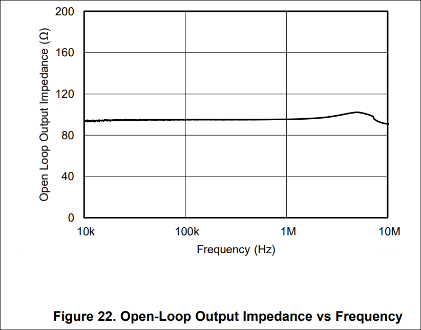
It is mentioned "Easier to Stabilize With Higher Capacitive Load Due to Resistive Open-Loop Output Impedance "

at Features on the datasheet.

What is the Resistive open-loop output impedance?

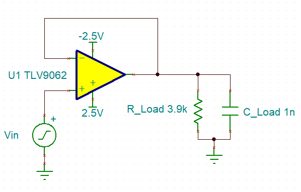
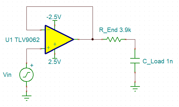
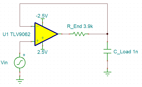
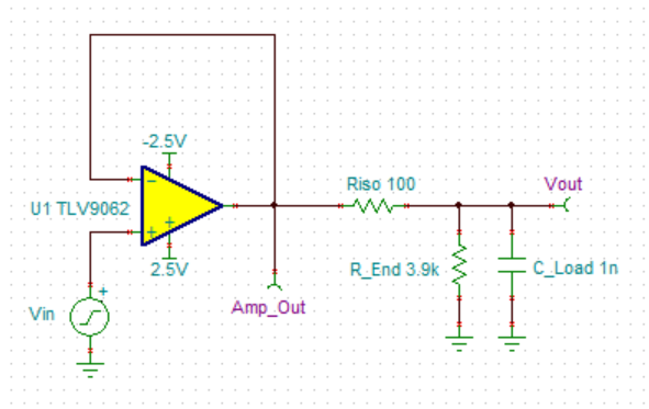
Does it mean insert the series resistor between output and load capacitance?

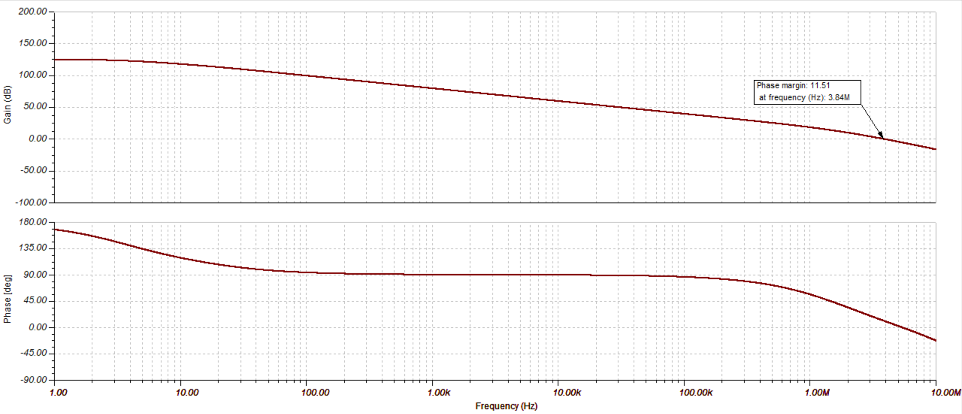
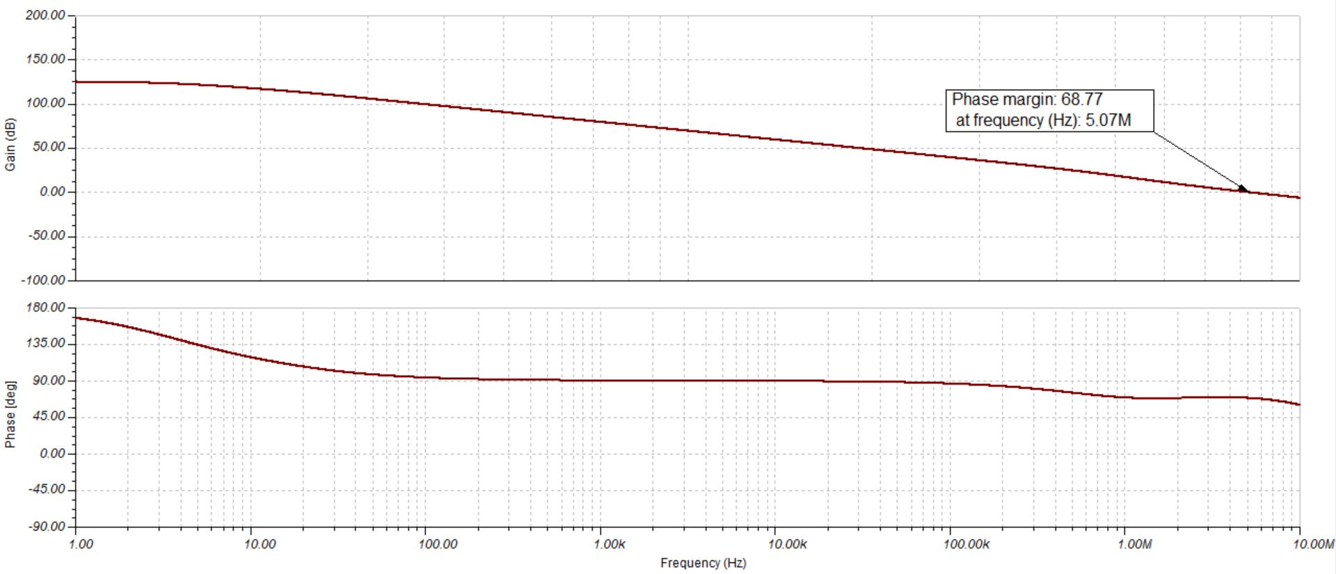
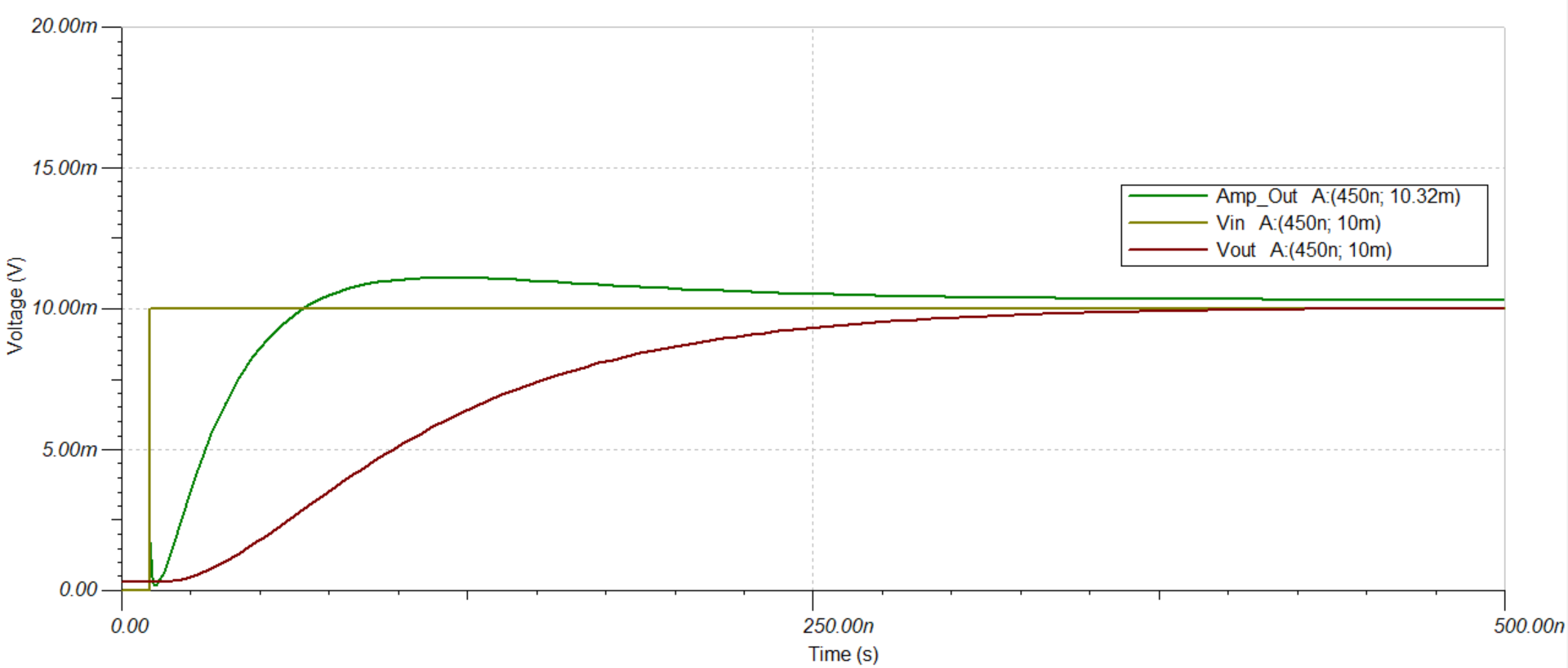
They use a long distance cable of more than 10m, so they are considering the stability of the TLV9062.

Best Regards,

Naoki Aoyama

  • Hi Naoki,

    this statement means that the open loop output impedance looks mainly resistive and not inductive, as with some other OPAmps. Neveretheless I would always put a resistor at the output of OPAmp to isolate the cable capacitance from the output of OPAmp. If a resistance cannot be tolerated at the output, because of the voltage drop across it e.g., I would put the isolation resistor into the feedback loop and use the double feedback method. Please see the stability training videos 1...6:

    training.ti.com/ti-precision-labs-op-amps-stability-3

    What load do you connect to the output of TLV9062?

    Kai
  • Former Member
    0 Former Member

    Hello Naoki,

    Kai is correct.  The phrase refers to an output impedance that is almost completely resistive.  In other words, the output impedance of the amplifier is constant across frequency.  The phrase is not referring to an extra series resistor at the op amp output.  This can be seen in figure 22 of page 20, where the open-loop output impedance is plotted versus frequency.  I have copied the plot here below.

    Depending on how large the output capacitance is, you may choose to add an extra series resistor at the output for stability reasons.  We call this an "isolation resistor."  For more information on using isolation resistors, you can look at TI's video/slides on this topic in section 10.5 of Op Amp Stability.

    Regards,

    Daniel

  • Hello Kai, Hello Daniel,

    Thank you for your reply.
    I understood "Resistive".

    I will ask the customer how about the condition of their load.

    Best Regards,
    Naoki Aoyama
  • Hello Kai, Hello Daniel,

    I checked the setting of the customer.

    Circuit: Voltage follower
    Signal : up to 100kHz sine wave
    C Load : 500pF - 1000pF
    End impedance : 3.9kohm

    Best Regards,
    Naoki Aoyama
  • Former Member
    0 Former Member in reply to NAOKI AOYAMA

    Hello Naoki,

    I am not sure where the end impedance is in this circuit.  Does it refer to the intrinsic impedance of the cable?  Here are three different possibilities.  Could you please tell me which one matches your circuit?

    I can then run a stability analysis and help if stability compensation is required.

    Regards,

    Daniel Miller

  • Hello Daniel,

    The first figure matches our circuit.

    Regards,
    Naoki Aoyama
  • Former Member
    0 Former Member in reply to NAOKI AOYAMA

    Hello Naoki,

    I have simulated your circuit and come to the following conclusions.

    First, I do not think your circuit will be stable without some type of compensation.  From my simulations, you will only have about 10 degrees of phase margin.  This is certainly not acceptable.  Below is the setup and the results of my stability analysis.

    Second, I would recommend you add an isolation resistor at the output of your op amp for compensation.  This will effectively create an extra zero in the response of the circuit.  The result will be much better stability.  I have run another stability analysis with a 100 Ohm resistor.  The results are shown below.  As you can see, the phase margin is much better at more than 65 degrees.  So, we would expect the isolation resistor to solve your stability issue.

    I have also simulated your circuit with an isolation resistor in two extra scenarios.  First, I was concerned that adding an isolation resistor might cause a significant voltage offset at the output of your circuit, as Kai has suggested.  This is the primary disadvantage of using an isolation resistor.  To test the effects of this, I have applied a 10 mV unit step input to the circuit and measured the resulting output voltage.  As you can see below, the simulation does not predict a noticeable offset due to the isolation resistor.  So, I do not think that you will suffer a significant voltage offset at the output due to the isolation resistor.

    Finally, I have run an AC response test to validate that the output of the circuit will remain close to 0 dB up to 100 kHZ.  As you can see below, the frequency response with the isolation resistor is quite flat.  This is good because is suggests that the gain of the circuit will remain constant across frequency, even with the isolation resistor.

    If you have any further questions or concerns, please let me know.  For more information on stability measurements, you can see training.ti.com/ti-precision-labs-op-amps-stability-3 For more information on the isolation resistor compensation method, you can look at training.ti.com/ti-precision-labs-op-amps-stability-5

    Regards,

    Daniel Miller

  • Hi Daniel,

    Thank you for your a lot of support.
    I will suggest the customer to insert an isolation resistor and evaluate well.

    Thanks,
    Naoki Aoyama