This thread has been locked.

If you have a related question, please click the "Ask a related question" button in the top right corner. The newly created question will be automatically linked to this question.

TINA/Spice/INA193: Minimum Differential input voltage range

Part Number: INA193
Other Parts Discussed in Thread: TINA-TI,

Tool/software: TINA-TI or Spice Models

Hi ,

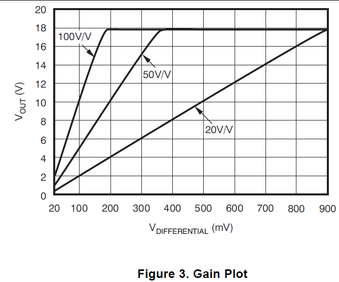
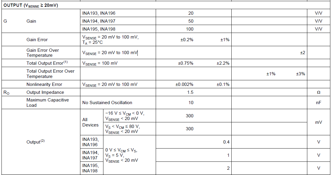
I'm using current Shunt Monitor for one of the automotive application, MIN and MAX differential voltage applying to  IC is  6mV  & 16mV  , the simulated output from TINA and theoretical calculation of the IC doesn't match. kindly can you recommend min and max differential voltage which can apply to IC

  • Hi Kishore,

    please see figure 3 of datasheet of INA193,

    Kai
  • Hello Kishore,


    Thank you for reaching out on the forum. We always hope to solve your issues.


    Anyway, there could be a number of issues in your simulation that might cause a deviation from the datasheet specifications, but as kai klaas69 has pointed out, Figure 3 is probably indicative of what you are seeing. The INA193 input differential voltage (Vsense) is limited by its dynamic output voltage range and this range is dependent upon what common mode voltage (VCM) is present at the input pins of INA193. According to specifications, if VS<VCM<80V and Vsense <20mV, then VOUT will saturate typically around 300mV. Additionally, we specify the gain error of this device for Vsense = 20mV to 100mV, thus we cannot assure the output will track the input if Vsense < 20mV and this is why your simulation may not be working.


    The absolute maximum Vsense is 18V according to table 7.1. The maximum full-scale input Vsense is (Vs-0.2V)/Gain at 25°C.


    Hope this helps,

    Peter Iliya

    Current Sensing Applications