This thread has been locked.

If you have a related question, please click the "Ask a related question" button in the top right corner. The newly created question will be automatically linked to this question.

OPA548: Sudden decrement in output despite constant input

Part Number: OPA548

Hello everyone,

I have been using OPA 548T to amplify a unipolar signal. The opamp was working fine till now.But, all of a sudden, the output voltage is reduced far below the input signal as well. Is it the case of a DEFECTIVE opamp or anything else?

Kindly suggest some solution.

Regards,

Dipendra

  • Hi Dipendra,

    maybe the thermal shutdown or the current limit became active?

    Kai
  • Hi Kai,

    Thank you for kind reply. I am using heat sink and monitoring temperature as well.Thermal shutdown is not the case for sure.Same ckt was working absolutely fine.The current limit is set to 3A. Max. current that can be drawn is less than 2 A.
    What may be alternative solutions/

    Dipendra
  • Hi Dipendra,

    It is possible that the OPA548 could have been damaged resulting in the unexpectedly low output level? Do you have another OPA548 you can try in the circuit?

    We are unable to diagnose the OPA548 application without a detailed circuit schematic and operating conditions information. Please provide the input signal, circuit schematic, power supply and output load information.

    Regards, Thomas

    Precision Amplifiers Applications Engineering

  • Hi Thomas,

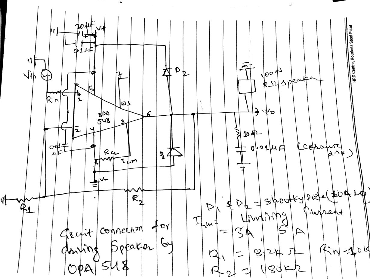
    Attached here is a circuit schematic.

    input voltage=1V,

    Amplification= 1 +R2/R1=~23,

    power supply = 28-30 V, 3.5 A

    Output voltage (expected)=23 but I am getting less than 0.5 v.

    output is a 100 watt speaker with Impedance=8 ohm

    As an input signal,i am giving a half square wave, a ground to positive trapezoidal signal.

    Initially, it was working absolutely fine with any such signal and above input paramet ers, But all of a sudden, the output decreased.I tried re-building the circuit and testing again.But, this doesn't seem to help.

    Thanks and regards,

    Dipendra

  • Hello Dipenda,

    Is the OPA548 V- pin really connected to ground? If so, that is a problem. With a dual supply the input is referenced to ground and the input and output signals are in the center of the op amp's linear operating range. If the op amp is set up with a single V+ supply then they must be referenced near mid-scale, or 1/2 V+ to assure operation within the linear input and output ranges.

    The circuit as seen applies the input signal to the non-inverting input which has a common-mode input voltage range (VCM) of (V–) – 0.2 to (V+) – 2.3. If the input signal is small and doesn't exceed the low-end VCM range that is okay as far as the input is concerned. The big problem is the output which is slammed up against the negative output swing limit and can only swing upwards from there. The OPA548 Vo negative is typically (V–) + 3.3 V for Io = 3 Amps. So the output is going to be slammed at +3.3 V until the input becomes positive enough to move it upwards and away from that rail. When the output is against a rail the op amp is not operating in its linear region and not really functioning as an op amp.

    If you have to use a single +V supply, AC couple the OPA548 input and output circuits. Use an input capacitor and a voltage divider to bias the non-inverting input at 1/2 V+. Add a capacitor in series with R1 as well, and a big capacitor in series at the output R2 connection to the load.

    Confirm the non-inverting and inverting inputs and output are at 1/2 V+ without an AC applied.

    Regards, Thomas
    Precision Amplifiers Applications Engineering
  • Hi Dipendra,

    8R loudspeakers have a somewhat lower DC impedance which can go down to 5R! 23V / 5R = 4.6A, much more than your power supply might be able to deliver...

    Kai
  • Hi Thomas,

    Thank you for such an illustrative explanation.But,I can use capacitor at input as it may lead to loss of the basic essence of the project,i.e. getting linear DC output.

    But agian, I'd like to draw your attention towards its proper working initially for the same ckt connection  as shown above.What may have caused the output slam?Is the OP-AMP damaged?How can I ensure this?

    Regards and thanks,

    Dipendra

  • Hi Kai,
    I checked its DC Resistance.Its=7.2ohm.With everything same, the OP-AMP was working fine for several days.So,I can say,this maynot be the problem.All I am curious is to know what caused this sudden problem at output.

    Regards and thanks,
    Dipendra
  • Hi Dipendra,

    for a test remove the loudspeaker, the 10R/10nF Zobel network and the Schottky diodes. Change R1 to 1k and R2 to 22k. Change Rin to 1k. Apply a DC voltage of 1V to the input. What output voltage do you see with a single supply voltage of 30V now?

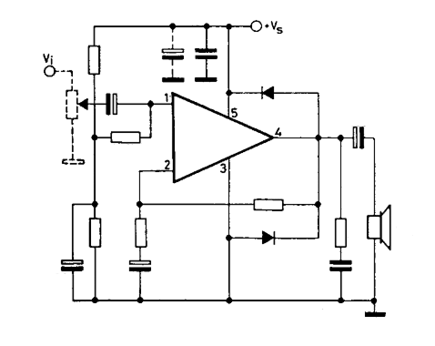
    But Thomas is totally right, your circuit looks really weird, if this is a typical audio application. Usually a bipolar supply voltage is used to drive a loudspeaker. If you choose a single supply voltage, on the other hand, you must bias the input with a midsupply reference voltage and use DC blocking caps at the input, within the feedback loop and at the output, like shown in this example:

    Kai

  • Hi Kai,

    This loudspeaker is not for an audio purpose. I am using this in a lab to produce a dc signal and signal <10 Hz. The speaker is being used an exciter. Can you please tell me how to confirm if the op-amp is really damaged?

    But,  one thing that's still driving me crazy is how could its output be slammed by such large amount, other conditions remaining constant. All the care was care for ESD and Heat sink.

    Dipendra

  • Hi Dipendra,

    you wrote: "Can you please tell me how to confirm if the op-amp is really damaged?"

    By what I wrote in my last post: "For a test remove the loudspeaker, the 10R/10nF Zobel network and the Schottky diodes. Change R1 to 1k and R2 to 22k. Change Rin to 1k. Apply a DC voltage of 1V to the input. What output voltage do you see with a single supply voltage of 30V now?"

    If everything is ok, then the output of OPA548 will show a voltage of 23V. If the OPA548 became damaged, on the other hand, then the output will very probably show a different voltage.

    Another test which I do always when I repair a hifi amplifier, is to check the collector emitter junctions of output transistors by the help of an Ohm-meter. So, measure the DC resistance between pin 4 and pin 6 and then between pin 5 and pin 6. A destroyed output transistor appears as a short circuit.

    Kai
  • Hi Kai,

    I tried doing that too. I am getting very low output as explained earlier. So I don't think Speaker is the culprit here.I also tried checking the resistance between the mentioned pins. It's not short-circuited for sure.Do you think the device is damaged now?

    Dipenda

  • Hi Dipendra,

    as Thomas already recommended, take a fresh OPA548 and check it again.

    Kai
  • Dipendra

    We have not heard back from you so we will close this thread. Please reply if further discussion is needed.

    Thanks
    Dennis