This thread has been locked.

If you have a related question, please click the "Ask a related question" button in the top right corner. The newly created question will be automatically linked to this question.

TLC3702: Unexpected behaviour when output of comparison is low

Part Number: TLC3702
Other Parts Discussed in Thread: TLC3704

Hello Amplifiers Forum.

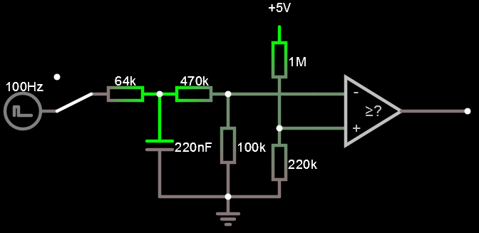
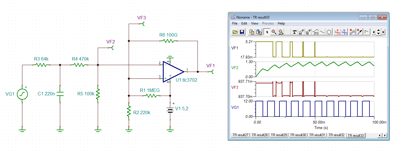
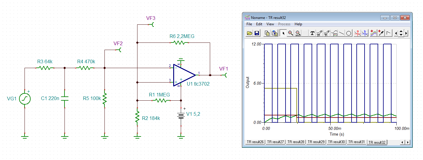
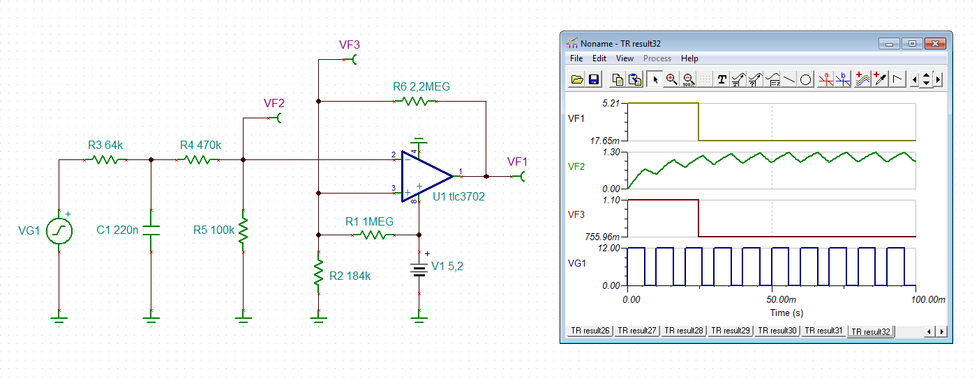
I am using a TLC3702 to compare a couple of input voltages, the values of which may be either 1.8 or 0V, to a common reference voltage of 0.8V. This common voltage goes to pins 3 & 6, while the external input voltages go to pins 2 & 5. Pin 4 is connected to ground and pin 8 to Vcc=5.21V.

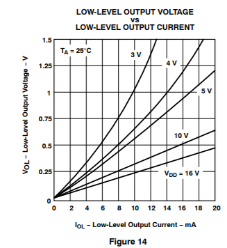
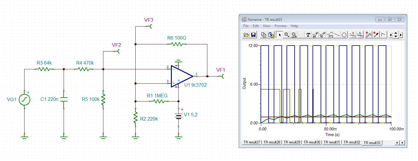
I have found that pin 7's voltage is either 0 or almost 5.2V, depending on which is the value on pin 5, the expected behaviour, however the voltage on pin 1 (1OUT) is either 5.2V for a high value (the expected) or between 0.3 and 0.6V for a low value (a bit higher than V.OL. in the datasheet).

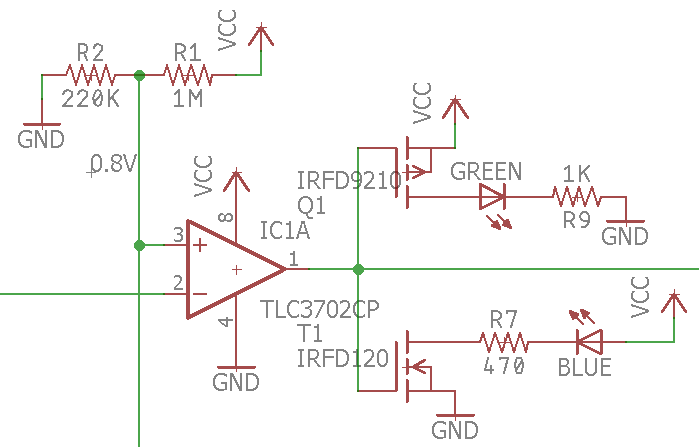
Then I connected a green led from Vcc to a 470 Ohm resistor into pin 1, and from there another resistor and finally a blue led into ground. The idea here would be that upon a high value on pin 1 the blue led would be lit, while the green one would remain off, and with a low value the green led would be lit, while the blue one would be off. The result of this was that when pin 1's value is high only the blue led is lit (the expected), however when pin 1 is low both leds are dimly on.

In order to try to improve this behaviour I modified the setup connecting pin 1 to the gates of two mosfets, one P-channel and the other one N-channel; the P-channel's source to Vcc, the P-channel's source to ground; finally the N-channel's drain to the green led, through the resistor and then to ground, and the P-channel's drain to the blue led from Vcc. Again, when pin 1 is high only the blue led lights up, and the green one remains off, however when pin 1 ought to be low, I read 0.6V and both leds light up, slightly dim.

If I dettach pin 1 from the gates and apply fix voltages to them, simultaneously, the setup behaves as expected: when I apply 5V only the blue led lights up, if I apply 0V only the green led lights up. I found out that the two transistors are open, and thus the two leds on, when I apply around 2V to their gates.

I hope I made myself clear, maybe the attached picture will help. I don't understand why pin 1 seems to output something between 0.5 and 2V when it ought to output less than 0.3V.

Thank you in advance & BR

  • Hi Adrian,

    looks like the internal n-MOSFET at the output of TLC3072 became damaged during the experimenting. Take a fresh TLC3702.

    Kai
  • Hello Adrian,

    What else is the output comparator driving? I see a trace running off the page from pin1.

    What if you drive the MOSFETS from pin 7?

    As Kai said, it sounds like the output is damaged and now has weak sinking ("grounding") ability.

    Your original circuit without the MOSFETS should work, and is fairly common.

    Looking at Figures 13 & 14, the output should be <0.25V with around 3mA.

    Try replacing the TLC3702.

  • Hi Adrian,

    Just would add additional info to Paul and Kai's reply. Since TLC3702 has a push-pull output stage, it could both sink and source current (see below). It smells like you have a defective part.

    But the Vol and Voh are functions of source/sink current as defined below. With that said, it should be able to directly drive efficient LEDs under which Vol and Voh could be derived from the charts.

    Best regards.

    Jian Zhang

  • Hello Kai, Paul, Jian, for your very kind replies.

    Following your suspicions I did some more testing, tried three other TLC3702s and even a TLC3704, they all exhibited the same behaviour. Then I tried the IC with an input which I governed (my original inputs to the TLC3702 are not) and doing so the IC behaved exactly as expected.

    What I believe is that the inputs are not really 1.8 or 0V, but are actually some PWM from 12V, of which 1.8V is the mean voltage, or high impedance. I apologise for this mistake. Unfortunately I don't have an oscilloscope. So, my reading of 0.6V in pin1 would actually be the result of my expected low result being high maybe 10% of the time.

    The trace running off the page is just going through a couple of Rs in order to reduce the 0~5V response to a 0~3.3V one.

    I modified my design with the one you can see below, and that way it works. The 64k resistor and the PWM are external to my design. Paul you were right, I don't need the external mosfets amymore. And Jian you were right too with the vol and voh, removing the leds the outputs are exactly Vcc or 0, with the resistors and leds the results go up or down about 0.5V, which means they draw around 7mA.

    Thanks again for you support and best regards.

  • Hi Adrian,

    as the ripple behind your ripple filter is still rather high, I would add a hysteresis:

    adrian.TSC

    Kai

  • Hello Kai.

    I had to look up what hysteresis means... after that I had to spend a long while analyzing your circuits, but I think I have understood them, and I have to say it's a very interesting suggestion. Good learning indeed.

    Best regards.