This thread has been locked.

If you have a related question, please click the "Ask a related question" button in the top right corner. The newly created question will be automatically linked to this question.

OPA541: Final Design

Part Number: OPA541
Other Parts Discussed in Thread: TL052

Attached find Altium 18.1.9 design files and dwg schematic in case you cannot read it.

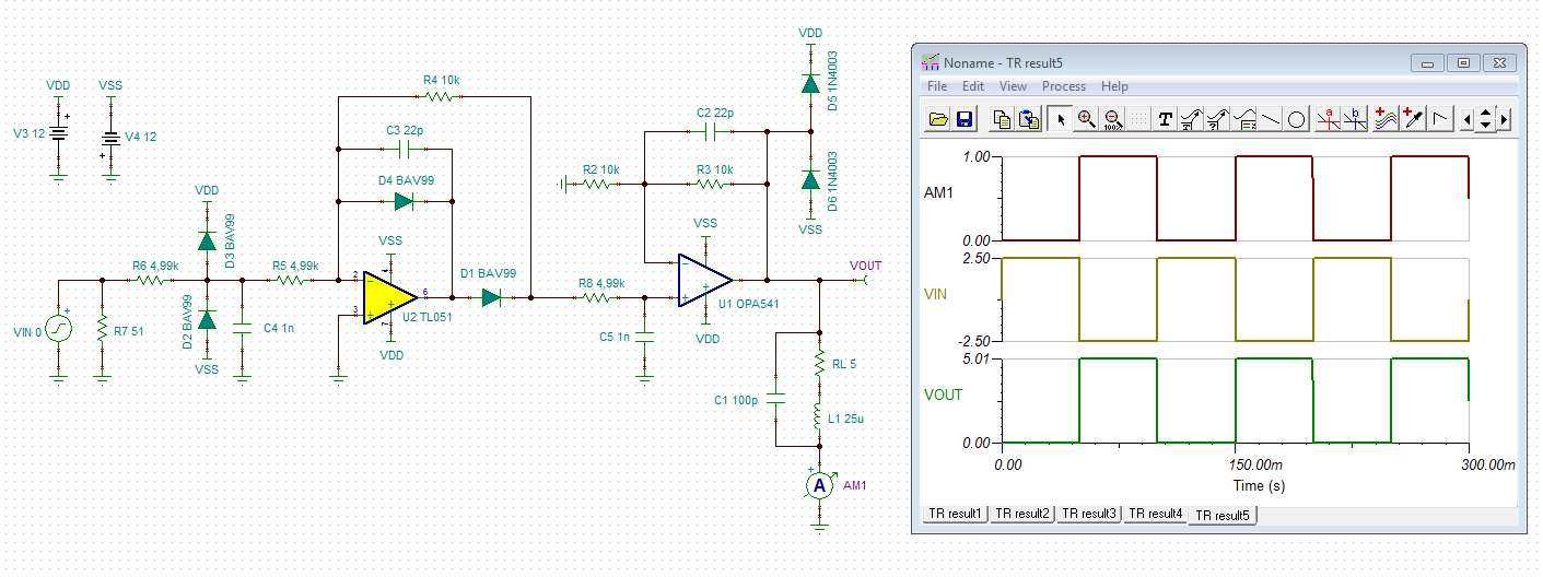
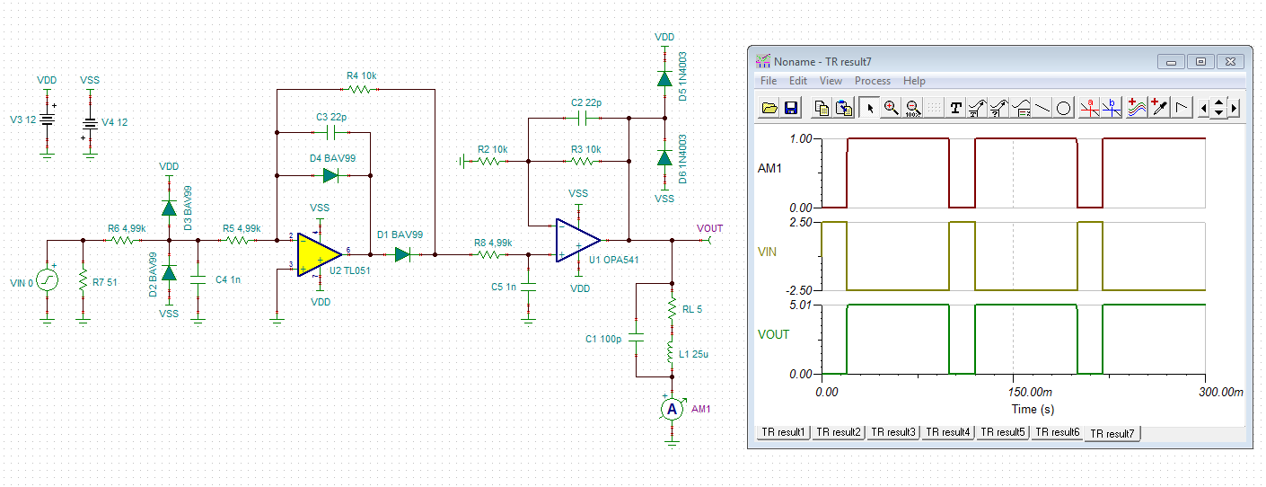
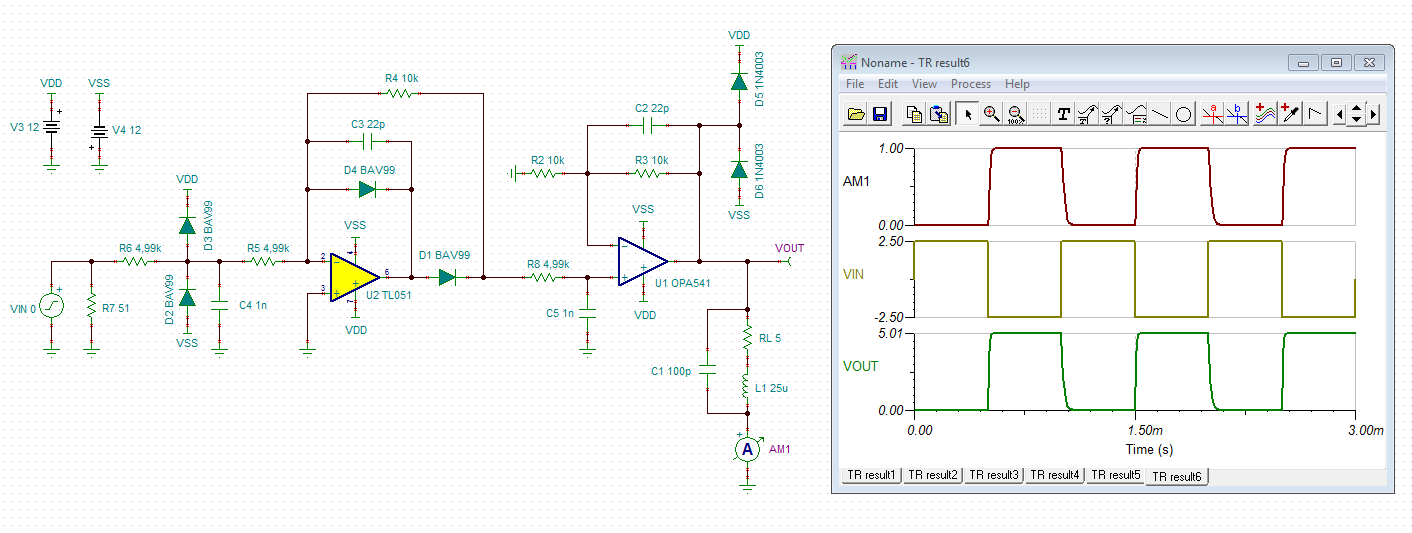
Kindly have a look at them and see if it makes sense for a simple four layer board similar to Figure 13 of the datasheet for a 25 uH 5 ohm Helmholtz coil pair requiring a .9 A peak current.

Of particular interest are the placement of R4 / current sense resistor and D1 and D2 diodes and output feedback connection location.

TI TECH SUPPORT POST OF JAN 24.docx

  • Tim

    The Altium files did not come through.
    It might be easier to use the Smart PDF function in Altium to create a pdf with the schematic and a separate plot of each layer. This would be a much smaller file and be readable by everyone.

    Regards
    Dennis
  • Thank you Dennis.

    I should have updated the request as this widow did not allow me to post them so I thought I posted the schematic and BOM.

    Here it is again.

    1803.TI TECH SUPPORT POST OF JAN 24.docx

  • Hi Tim,

    I would add a precision single wave rectifier to the input of OPA541 as shown below. This would allow you to generate a true unipolar signal at the Helmholtz coil without having to adjust the offset voltage whenever you change the amplitude at the function generator. The single wave rectifier takes the negative going part of the symmetrical square wave signal and transforms it into a positive going square wave. The output signal is a true unipolar square wave.

    The first simulation shows the performance of a 10Hz square wave: (Your 0.4R current limiting resistor isn't shown in the simulation, because the model has no connections for it.)

    The next simulation shows a 20% / 80% duty cycle:

    The next simulation shows the performance of a 1kHz square wave to demonstrate how the edges are rounded and smoothed and that there's no ringing:

    Some words to the circuit: R51 terminates the 50R cable coming from the function generator. In most cases it can be replaced by a higher ohmic resistor (10k or so). Diodes D2 and D3 perform a protection circuit for the TL052, when the TL052 isn't powered but an input signal is applied. R6 limits the current through these diodes. It also serves as a low pass filter in combination with C4. OPAmps don't like input signals with all too steep edges. Another low pass filter is R8 / C5. The corner frequency of these low pass filters is above 30kHz. So, it will not hurt your 10Hz square wave signal at all.

    With this circuit you can adjust the amplitude and duty cycle at the function generator. And there's no need to adjust the offset, because this circuit automatically generates a true unipolar suqare wave across the Helmholtz coil.

    tim2.TSC

    Kai

  • Thank you Kai.

    Unfortunately your reply does not answer any of the questions I have on the final design asked in the previous post.

    Kindly let me know if it answers the following questions.

    Pull up resistor location, 5K value, and 1/8th watt rating.

    Current sense location, 400 mohm value for 2 A limit, and 1 watt rating.

    Schottky diode location,  200 V peak repeatable, 3 A rating with the 25 uH 5 ohm Helmholtz coil.

    Feedback resistor 10Kohm 1/4 watt rating.

    Please know your work is not a waste of time as the project scientists many times change their minds.

    For now unipolar current is not a requirement and I apologize if I said it was a requirement.

    I will certainly use your expertise if the requirement changes.

    I look forward to continuing the dialog.

    One last question.

    Would 50 kohm resistors be better.

    One of my past colleagues makes it a design rule to have at least 50 kohms input impedance.

  • Hi Tim,

    a pull-up at the +input of OPA541 makes no sense. If you plan to run the OPA541 as inverting amplifier powered by a bipolar supply voltage, you should connect the +input of OPA541 to signal ground (RTN in your schematic) or to a reference voltage that does not violate the common mode input voltage range.

    Yes, a 0R4 resistor can be used for a current limit of 2A (AP version). Worst case heat dissipation will be (2A)^2 x 0R4 = 1.6W, though. So, a 1W resistor is not adequate! I would take a 3W or 5W resistor, depending on your duty cycle range and cooling situation.

    Schottly diodes' location and diode ratings are correct.

    1/4W rating for the 10k feedback resistors is correct.

    No, 50k feedback resistors are not better.

    Kai