This thread has been locked.

If you have a related question, please click the "Ask a related question" button in the top right corner. The newly created question will be automatically linked to this question.

THS6022: there exit 20mV offset when the IN+ is floating

Part Number: THS6022

Dear Kai,

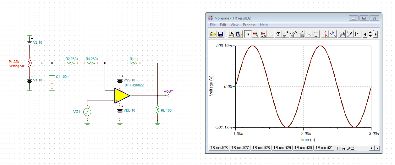
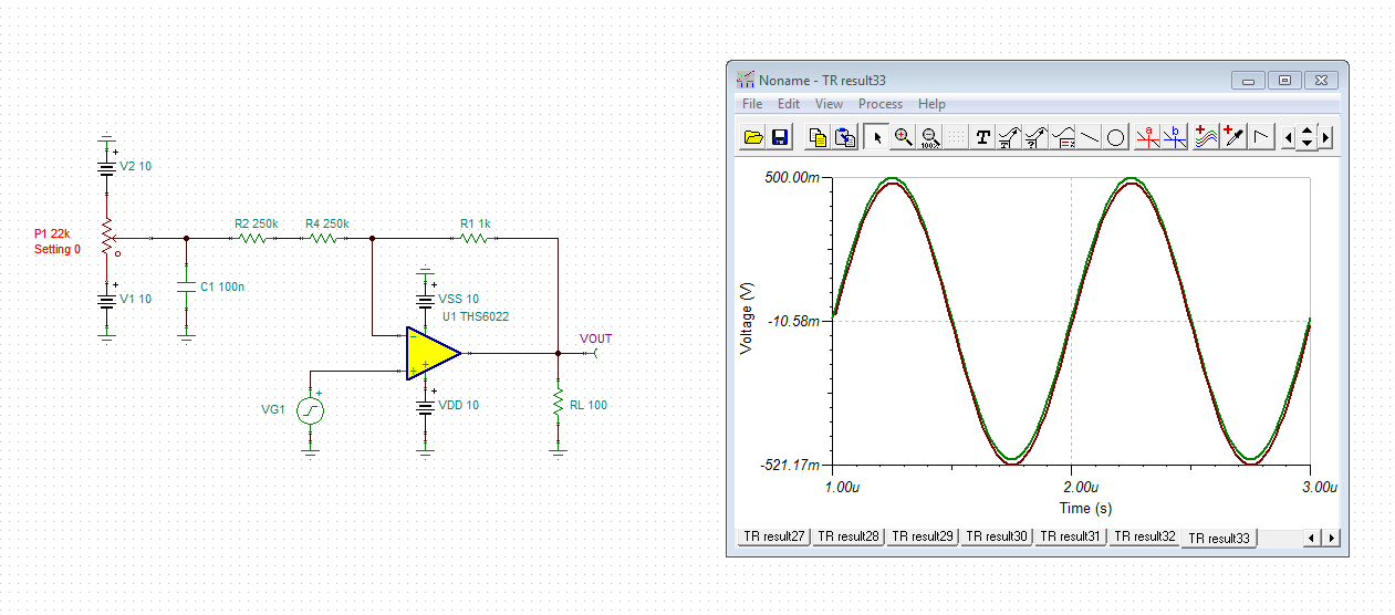
    Thank you very much for this useful suggestion. I duplicated the scheme you provided. And I have achieved my function. By the way, there have about 20mV offset even though the IN+ is floating as shown in the Figure 2. Refering to the datasheet, the maximum offset should be about 5~7mV when gain=1. Do you know how to reduce this offset? Cause our project demand the offset is below 10mV.

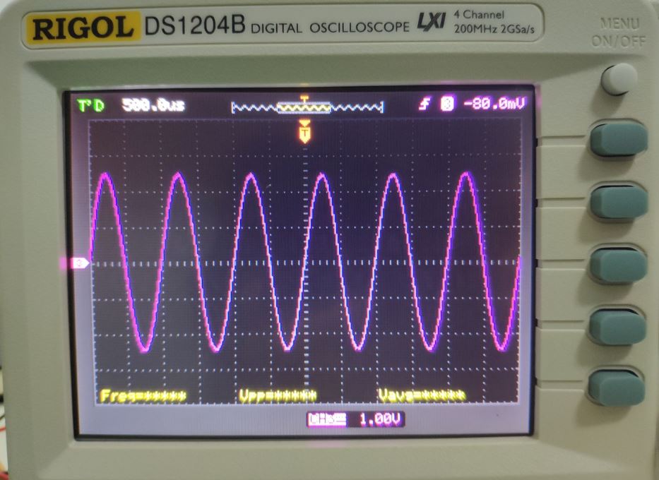
Figure 1: The function is exactly what I want

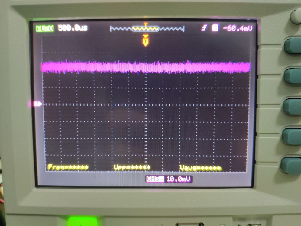
Figure 2: there exit about 20mV offset

  • Hi,

    can you show a schematic please?

    Kai
  • Hi Kai,

        FYI, thanks!


  • Hi,

    only to avoid any misunderstanding, RL = 50R in figure 2 of datasheet of THS6022 is exemplary for a load connected to the output of THS6022. Or by other words, if you have real loads connected to the outputs of your THS6022, then there's no need to add R3 and R4.

    Keep in mind that the THS6022 has input bias currents. They flow into the input pins and cause voltage drops across the resistances they see at the inputs. For instance, the input bias current flowing into the -input runs through the feedback resistance and causes a voltage drop which appears as additional offset voltage at the output of THS6022.

    HF OPAmps are optimized for high speed and not for higesht DC precision and in HF applications offset voltages play an minor role, usually. But if low offset voltage is strictly required in your application, you can add an offset adjust scheme as shown below:

    As you can see an adjustment range of +/-20mV is provided here.

    Such an offset adjustment scheme needs a very careful layout in order to keep the additional stray capacitance at the -input pin low. Too much stray capacitance can decrease the stability of OPAmp by eroding the phase margin. Using two resistors R2 and R4 instead of only one can help to minimize the stray capacitance.

    ths6022_offset.TSC

    Kai

  • Hi Kai,
    Thanks for your essential support.