This thread has been locked.

If you have a related question, please click the "Ask a related question" button in the top right corner. The newly created question will be automatically linked to this question.

INA199: Input terminal has leakage current?

Part Number: INA199
Other Parts Discussed in Thread: TPS568215

Hi guys

Our customer is using our INA199 as server PSU output current sense. Common mode voltage is 12V. and the power supply is 16V-GND and REF is tied to GND. But we found an issue about INA199 input:

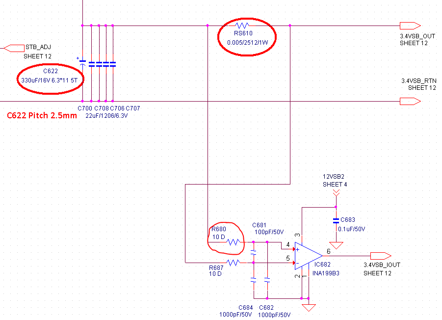
schematic:

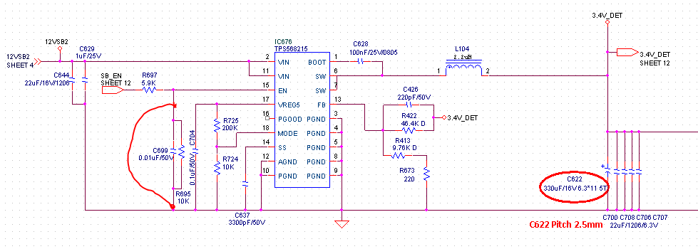
The output current sense circuit is like above. Every time we power on, we can control the TPS568215 EN Pin is low(which means disable the buck output, so the output should be GND). But we found the output will be 2V. It is not be GND(0V). 

Firstly, we thought it is related to the buck device. But we test the SW pin of the TPS568215. We found the SW have no any signal(PWM). 

Secondly, We removed the inductor L104. So the Buck device will separated to the output circuit. But we found the output voltage(INA199  IN+) will still be 2V.  Here I don't know what lead to the INA199 INPUT common mode voltage 2V. There is no any other connections except the buck device and the INA199.

Thirdly, we removed the R680 and R687,  the output voltage will be GND.

Do you have any recommendation about this issue?

Any feedback will be appreciated.

Thanks 

-Pengfei

  • Hi Pengfei,

    the INA199 has a rather high input bias current. This can generate a voltage drop across R422, R413 and R673. A low ohmic pull-down resistor from 3.4V_DET to GND can reduce this voltage drop.

    Kai

  • Hi Kai
    thanks for your response.
    The 20uA is for 12V common mode voltage. But our test condition is at 3.4v common mode. Especially for this issue, we have disable the buck converter, the common mode voltage is about 0V. So at this condition, it is also have 20uA Ibias? do we have simulation mode for this one? If it is that the Ibias leads to this issue. Do we have a P2P part to solve the problem?
    Thanks
    -Pengfei
  • Hi Pengfei,

    see figure 8 of datasheet.

    If you measure 2V, then the INA199 sees 2V common mode voltage, regardless of whether you have disabled the regulator or not. The INA199 would create the common mode voltage by itself, by the help of input bias current.

    But usually there is a load connected to the output of regulator which would absorb this input bias current. Isn't there any load connected to the output of regulator in your application?

    Kai
  • Hey Pengfei,

    This is certainly peculiar/incorrect device behaviour. Is there any chance that the capacitors C622, C700, C706, C707, C708 are not holding the 2V charge? Is the 2V stable or is it slowly decaying? Is this happening with every system? How many systems built are showing this behaviour?

    Is there a voltage potential difference between the ground of INA199 and ground of TPS568215? Ensure that all different ground planes are connected through low-impedance connections. It's important that the inputs to the INA199 have a DC input current return path. In other words, the input pins (IN+, IN-) need to be connected to some common anlaog ground or else they are essentially floating if there is no return path to ground downstream on the 3.4VSB_VOUT rail.

    After ensuring no ground potential differences you can debug with the following:
    First remove C684, C682 and repeat the experiment. These capacitors are rarely needed and will only contribute more error.
    Then try placing a 10kΩ to 34kΩ resistor to ground at IN+ pin. Disable circuit and see if 2V remains.

    Please post back with any updates.

    Best,
    Peter Iliya
    Current Sensing Applications
  • Thanks Peter. As you said, this issue is not from our device, I checked their circuit again. I found that there is a Oring circuit at another one board. And through our test, I found this 2V is from their Oring solution. So far we can close this issue.
    Thanks
    -Pengfei