This thread has been locked.

If you have a related question, please click the "Ask a related question" button in the top right corner. The newly created question will be automatically linked to this question.

TINA/Spice: Pre-amplifier Circuit to amplify 0.1 micro volt sound echo signal into few volts of specific frequency

Other Parts Discussed in Thread: TINA-TI, INA103, INA163, UAF42

Tool/software: TINA-TI or Spice Models

Hello,

I need to make an pre amplifier circuit for receiving sound echos from atmosphere which is in range of 0.1 micro volts to 10 micro volts. Current design consist of one transformer coil in the starting to step up the voltage level and then used universal active filter and opamp to amplify and filtering purpose. Can you suggest me any TI instrument which can perform on these range amplification with good SNR.

Regards 

Parag Chourey

  • Hello Parag,

    The difficulty in amplifying such low-level microvolt signals is dealing with the intrinsic noise of the amplifier, and the extrinsic noise that will get into your circuit. Probably your best bet is to use a high-performance, very low noise instrumentation amplifier such as the INA103, or INA163, and then follow it with the active filter/gain stage. Note that there very low noise instrumentation amplifiers have higher input bias current than others, but that is due to the low noise design.

    You can find the INA103 and INA163 datasheets here:

    www.ti.com/.../ina103.pdf

    www.ti.com/.../ina163.pdf

    Here is a link to another e2e discussion that discusses an application that is similar to yours:

    e2e.ti.com/.../293906

    You will have to take precautions to keep external noise from entering and corrupting your very low signal levels. You will likely need to enclose the circuit in a metal box, and power it from battery sources. Shielded cabling will be a necessity.

    Regards, Thomas
    Precision Amplifiers Applications Engineering

  • Hi Parag,

    the key parameter in low noise applications is the source impedance. An ultra low noise circuit for a low source impedance will usually look totally different than an ultra low noise circuit for high source impedance. For a low source impedance you will take an amplifier providing a very low input noise voltage, while the input noise current is a bit of less interest. For a high source impedance, on the other hand, you will take an amplifier with very low input noise current, while the input noise voltage can be a bit higher.

    Transformers can help to move the source impedance into the range where the OPAmp has it's noise optimum.

    Kai
  • Hello thomas,

    Thanks for your valuable response. I will take care of all your instructions and acknowledge you about result. 

    With Regards,

    Parag

  • Hi Parag,

    can you tell more about your microphone and its source impedance?

    Kai
  • In addition consider downloading the free SPICE simulator from TI, TINA-TI at:

    http://www.ti.com/tool/tina-ti

    By building and simulating your circuit in TINA-TI many problems can be avoided before building it in the real world. If you have problems once the circuit is built in TINA-TI feel free to post the schematic from TINA-TI on the E2E Forum for further assistance.

    We assume this resolved your issue. If you need to ask further questions you can post a new “Reply” or start a new post if it is an unrelated issue.


  • Hello Sir,

    I am using the same electro-acoustic transducer (loud speaker) for transmitting and receiving purpose. Transducer has an 16 ohm of internal impedance. The receiving signals are point of concern which are very less in amplitude. 

  • Hi Parag,

    with a source impedance of 16R you should search for "moving-coil pre-amplifier". These have the lowest noise.

    16R means a noise voltage density of SQRT(4 x k x T x R) = 520pV / SQRT(Hz) resulting from resistor noise. The pre-amplifier should have a input voltage noise density which is not higher than this value.

    520pV / SQRT(Hz) corresponds to a noise current density of  520pV / SQRT(Hz) / 16R = 32pA / SQRT(Hz). So, your pre-amplifier should have a input current noise density which is not higher than this value.

    You could use the INA163. This OPAmp has an input voltage noise density of 1nV / SQRT(Hz) and an input noise current density of 0.8pA / SQRT(Hz). But from this data you can see, that it's not optimum for a 16R source impedance. It's optimized for 200R source impedance. A remedy could be to shift the 16R source impedance by the help of a 1:3.5 audio transformer. Then the INA163 would see an impedance of 16R x 3.5^2 = 196R and would run at its noise optimum.

    As far as I know a audio transfomer will still give the lowest noise, even today. But a good audio transformer is costly.

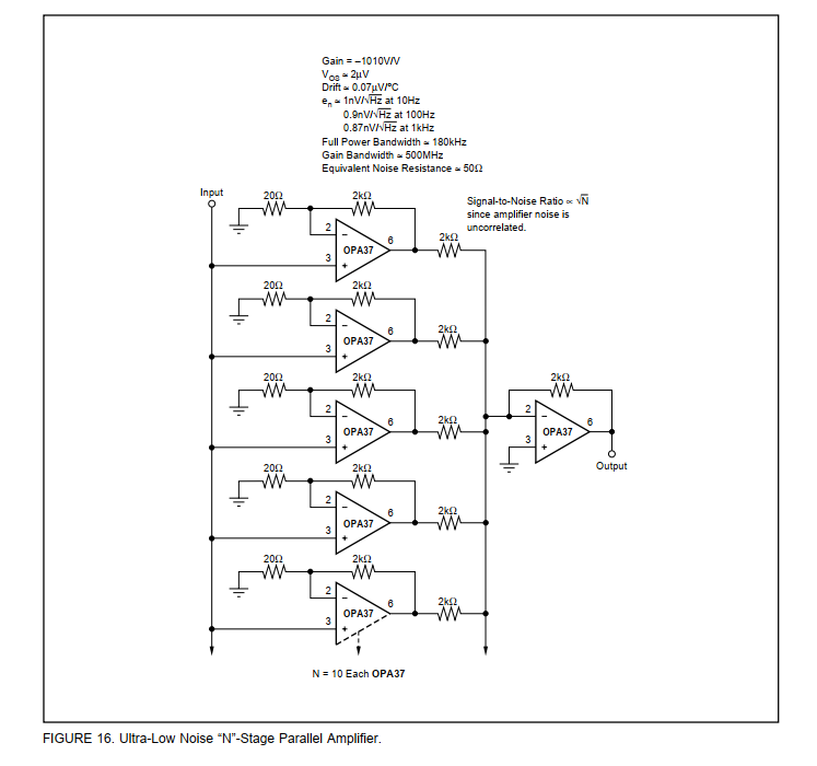
    Another trick is to put several INA163 in parallel, as shown here:

    An alternative method is the use of an OPAmp with paralleled discrete transistors at the input to enhance the noise performance. Such a circuit can offer an input noise voltage density of about 300pV / SQRT(Hz).

    Kai

  • Hi sir,

    Thanks for this information. It really helps me out. I think INA163 will work for me. I am in a search of good audio transformer now as you suggested and will use UAF42 for band passing the amplified signal in later stage. I will update you about my circuit when it completed. Your detailed answer gave me lots of learning so again thank you.
  • Hi Parag,

    if you want to simulate the circuit with TINA-TI, then you should use the UAF42E model, not the UAF42 model. See also here:

    e2e.ti.com/.../767538

    Good luck! :-)

    Kai