This thread has been locked.

If you have a related question, please click the "Ask a related question" button in the top right corner. The newly created question will be automatically linked to this question.

OPA388: Oscillation at roughly 370kHz at the output pin

Part Number: OPA388

Hello E2E community,

In a recent project i am using the OPA388 as an Integrator.

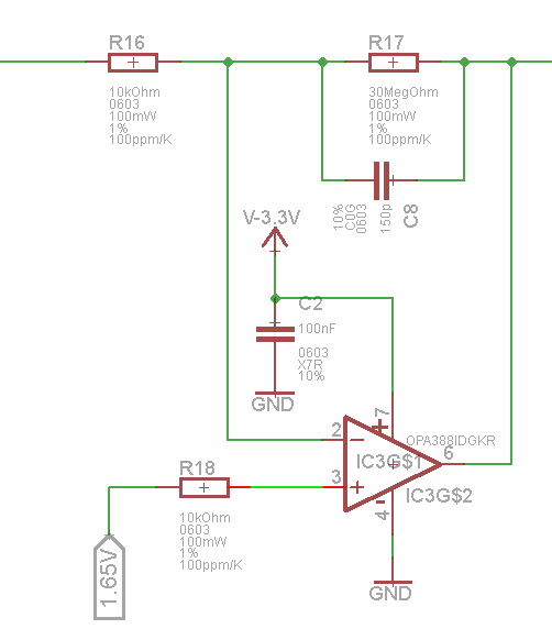
The output pin is connected to a 150pF capacitor and a high resitance resistor in parallel to it.

The other side of the capacitor is connected to the negativ input pin.

My problem is, that there is a osccilation at round about 370kHz at the output pin even without an input signal.

Is this the frequency of the internal charge pump or any other component, or is it a problem in my setup?

When disconnecting the power to the op the signal is gone.

Regards,

Dennis

  • Hi Dennis,

    can you show a schematic?

    Do you have a DC/DC converter in your setup?

    Kai
  • Hi,

    No there are no DC/DC converters on the board.

    The circuic is directly powererd from a linear bench power supply.

    I have already checked the input voltage for any noise / ripple.

    But I think i have identified the problem.

    I thought there is no problem on the non-inverting input pin of the op-amp, but after connecting the output and another oscilliscope probe to the scope i noticed that the probe itself removes the problem when connecting it to the input pin.

    Maybe the 10k bias current compensation resistor is not good in this case.

  • Hi Dennis,

    I would try to add a 100n filtering cap from the +input to GND.

    By the way, what is connected to the left side of R16?

    Kai
  • Hi Dennis,

    This DSO image doesn't show the characteristics of a loop instability issue with the damped or continuous oscillation obtained when there is one.

    The OPA388 uses a chopper architecture and the chopping frequency is roughly 180 kHz, about half the 370 kHz ripple you are observing. It's probable in an integrator application that the input current charge injection associated with the input chopping switches is being amplified and appears at the output. It is hard to say why the ripple would be at 2x the chopping frequency but there are multiple switching operations occurring internal to the OPA388 that may explain why.

    There really isn't any reason to add a resistor in series with the OPA388 non-inverting input. It does nothing to improve the voltage offset as with some older non-chopper op amp circuits, and it enhances the input current charge injection effects by converting the current to a voltage. I expect that if you remove that 10 kohm resistor and replace it with a short, or add the capacitor to the input as Kai suggested that the ripple will be much reduced, or eliminated.

    Regards, Thomas
    Precision Amplifiers Applications Engineering
  • Hello Thomas,

    Thanks for your answer.

    You are right, when i remove the resistor, the ripple is gone.

    But isn't it a common practice to add a resistor to the non-inverting input to match the resistance on both inputs and compensate the bias current?

    Or is this a technique only for older OpAmps with much higher input currents?

    Regards,

    Dennis

  • Hi Dennis,

    It was a more common practice when most op amps employed bipolar transistors in the differential input stage, but doing so is not needed for JFET, CMOS or bipolar inputs with input bias current cancelation.

    You can read more about the question of adding the series resistor to the non-inverting input in a blog by Bruce Trump, a former TI Precision Amplifiers applications manager. He explains the subject beautifully. You can find his blog here:

    I am glad removing the resistor and using a direct connection resolved the OPA388 ripple issue. If you can close out this inquiry now we would appreciate it.

    Regards, Thomas

    Precision Amplifiers Applications Engineering