This thread has been locked.

If you have a related question, please click the "Ask a related question" button in the top right corner. The newly created question will be automatically linked to this question.

TINA/Spice/OPA657: Low noise resonant photodiode

Part Number: OPA657

Tool/software: TINA-TI or Spice Models

Hi,

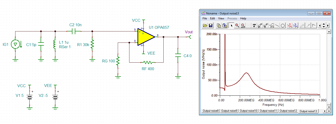
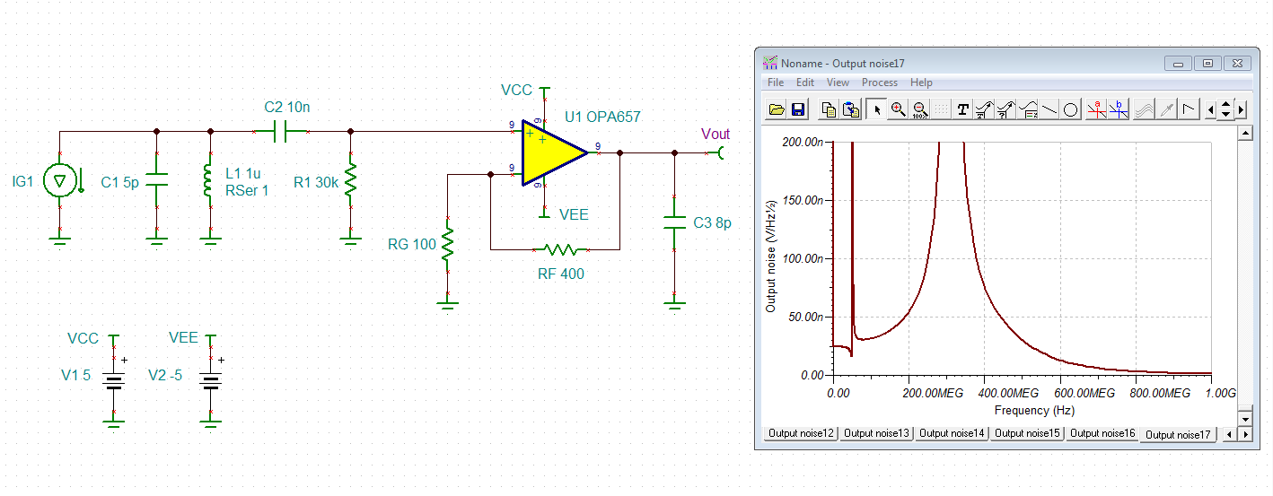
I am trying to build a resonant photodiode with an operational freqeuency between 50-100 MHz with low input referred current noise (<1pA/sqrt(Hz). Using the opa657, my spice model shows it should be possible reach the thermal noise limit of ~0.8pA/sqrt(Hz) set by the 30k resistor (See schematic below), but in practice I measure  noise at the 5 pA/sqrt(Hz) level. Care was taken to minimize feedback path lengths and reduce parasitic capactitance and the board is also enlcosed in a grounded case. I am just wondering if I may have overlooked something in my design. Any input would be greatly appreciated, thanks in advance.

-William

  • Hi William,

    could the noise come from the photodiode itself? Photodiodes can become very noisy, if a bias voltage is applied and the leakage current is swelling.

    Kai

  • Hi Kai,

    Thanks for the reply, its a good point. The diode I am using (Hamamatsu S5973-02) should have a dark current at the pico amp level, so any fluctutions (either from shot noise or bias supply) should be neglible, hopefully.
  • Hi William,

    what about the bias voltage itself? Is it noisy?

    Kai
  • Hi Kai,

    It should be low noise at the resonance freqeuency, C3 should also help with filtering. I tried powering the board from a bench top supply and batteries and it made no difference.

    William
  • Hi William,

    How are you measuring the noise? Could it be voltage noise? Sometimes noise and parasitic DC currents at these sensitivities can come through the PCB bulk. Some designs use a Vref loop around the photodiode output to shield it from the rest of the board.

    Best regards,

    Sean
  • Hi Sean,

    I figured out the noise by measuring the NEP using an intensity stabilized laser beam. I increased the intensity until the photo current shot voltage noise matches the electrical voltage noise. Using the photo diode responsivity (in units of A/W) I can back calculate what current this power should induce. I have also verified the responsivity by measuring the DC response using another TIA circuit. I also checked that  RIN on the laser is negligible at the resonant frequency.

    I was wondering if it could be input current noise on the op-amp at higher frequencies. The datasheet for opa657 has the current noise being flat all the way to 10M (fig. 13), while most JFET op-amps have current noise that starts to climb at higher frequencies (e.g. OPA 858). I wanted to try and measure it at high frequencies, but I could not figure out how to get around the problem of it being filtered by the parasitic capacitance on the input.  

    Cheers,

    William

  • Hi William,

    have you considered the influence of capacitive load?

    william.TSC

    Kai

  • Hi Kai,

    Thanks for taking the time to simulate the circuit and looking into the issue, much appreciated. Yes, we noticed this was a problem when testing the prototype (we saw different noise performance  depending on the length of cable connecting to the spectrum analyzer). We have since added a 50 ohms output termination and the problem went away. Sorry, I should have mentioned in the original post. The other two places a relatively small parasitic capacitance can have a drastic effect is excess common mode capacitance on the input pins and if there is any coupling between the output and positive feedback pin (not too surprising). 

    The other circuit variation we tried is moving R1 (in your circuit)  into series with L1. In this case the effective transimpedance is enhanced by the resonance and the resistor only needs to be a few ohms. We also have a working design this setup, but the noise performance is comparable. 

    Cheers, 

    William