This thread has been locked.

If you have a related question, please click the "Ask a related question" button in the top right corner. The newly created question will be automatically linked to this question.

INA226 detecting wrong shunt voltge

Other Parts Discussed in Thread: INA226, ISO1541

I am using INA226 for -48 v telecom bus high current measurement so that Rshunt used is 0.2mohm 1%  for testing purpose I am using -12V supply for with 24 ohm resistor load. voltage drop across Rshunt for 0.500mA current should be 0.1mV but INA226 detecting Shunt voltage is 0.140V and for -24V 24 ohm resistor load voltage drop across Rshunt for 1A current should be 0.2mV but INA226 detecting 0.270mV due to this I am getting wrong current values in current register. I am setting Calibration reg 2055 and current LSB is 0.01245117 and max current expected is 408.60A for given Rshunt 0.2mOhm.

  • Hi Vivek,

    What is the raw register value that INA226 reports back in both cases? Do you see large variation when multiple measurements are taken? If the measurements are stable and repeatable, have you measured the differential input at the INA226 to see if it is what you expect and further if it correlates with what INA226 reports back?

    Regards, Guang

  • I measured differential input at INA226 it is for -12v 0.1mV and for -24v it is 0.2 mV using 24 ohm load. And Raw values received in first case is 112 and second it is 218. not seen large variations when multiple measurements taken
  • Hi Vivek,

    The measurements are too much off. Do you mind posting relevant schematic here?

    Regards, Guang

  • Hello Guang,

    Thank you for response and I am very sorry for giving wrong values previously as they are obtained correct connections.

    But after debugging that issue and correcting read write into INA226 I took  following reading on INA 226

    Config Reg value : 0x9FF

    Rshunt = 0.0002 ohms so Maximum expected current will be 409.6

    Current_LSB = 0.0125

    Calibration reg = 2048

    please verify these setting also attached schematic for this design

    test condition 1 : 12v and 24 ohm load expecting 500 mA  current through Rshunt and 0.1mV drop across it

    Actual reading from meter are 482 mA  0.122mV drop across Rshunt

    Raw values read from INA226  

    Shunt reg = 0x38

    Bus voltage reg = 0x981 (3.041 refer schematic for this value)Current Sensor.pdf

    current reg = 0x38

    final current value according to this will be 0x38 * Current_LSB(0.0125) = 0.7 A  which is not required current value.

    test condition 2 : 24v and 24 ohm load expecting 1A  current through Rshunt and 0.2mV drop across it

    Actual reading from meter are 915 mA  0.213mV drop across Rshunt

    Raw values read from INA226  

    Shunt reg = 0x6C

    Bus voltage reg = 0x123E (5.81375 refer schematic for this value)

    current reg = 0x6C

    final current value according to this will be 0x6C * Current_LSB(0.0125) = 1.35 A  which is not required current value.

    So please help me with this process to get correct values from sensor.

    Thanks and Regards 

    Vivek Borse

  • Hi Vivek,

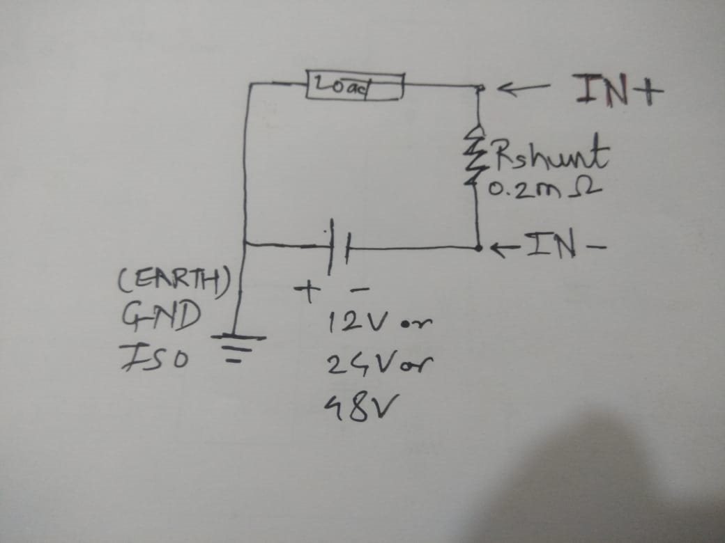
    Not a problem. Can you please label on the schematic (hand drawing is OK):

    (1)   How the 12V (or the 24V) source is connected

    (2)   How the 24Ohm load is connected

    (3)   How the GND_ISO is connected and what is the relationship with GND_INA

    Based on the metered shunt voltage, the INA226 reported current values are somewhat close within about 10%, it is better, although not great.

    Regards, Guang

  • Hello Guang Zhou,

    please find in attachments connection diagram of my current sense setup

    GND_ISO and GND_INA are isolated 

  • Hi Vivek,

    Looks like the attachments didn’t come through, can you try again.

    Regards, Guang

  • this is the wiring diagram

  • Hi Vivek,

    How is GND_ISO connected? I understand you said it is not connected to GND_INA, but is it connected to earth ground or left floating? How is the INA226 supply generated? Where is it referenced to?

    I think you should get correct readings if you leave GND_ISO floating. Since you didn’t say, I assume it is, but then the VBUS measurement doesn’t make sense at all. It should be almost 0V, instead of several volts.

    I strongly encourage you make some hand measurements with respect to GND_INA, including on the IN+ and VBUS pins.

    Regards, Guang

  • Hello Guang Zhou,

    Did you look my schematic and my wiring diagram then you can see that I generated INA226 supply using Z1 and R5. which power INA226 and ISO1541.

    I am connecting GND_ISO connecting to earth (wiring diagram) ,if it is not connected to earth ground then INA226 is not power up not responds to I2C communication.

    I did measure with respect to GND_INA on IN+  and VBUS when GND_ISO is floating no voltage is observed on these points.

    When I connected GND_ISO to earth with respect GND_INA and Vbus is 3v and GND_ISO and IN+ is 0.106mV .

  • Hi Vivek,

    You said before that the measurements are repeatable, but please be sure to take a few more and see what the variation is. Based on your Feb 9th post, the measurements are not too far off. Remember that INA226 measures a voltage; it has not idea of a current. You’ll have to use the hand-measured shunt voltage as the bench mark, not the current meter reading. 

    Also you can try increasing the load current to see if the accuracy improves. Generally speaking it should.

    Regards, Guang

  • Guang Zhou

    I mentioned in that post the shunt voltages measured with meter for both conditions which are not matching with INA226 readings.

    for test condition 1 : shunt voltage is  0.122mV using voltmeter and reading from INA226 of shunt register is  0x38 

    for test condition 1 : shunt voltage is  0.213mV using voltmeter and reading from INA226 of shunt register is  0xC6 

  • Hi Vivek,

    Hopefully more testing can provide some clues, because I don’t see anything that is obvious at this point. You can do the test without the load resistor and shunt resistor. This will make it easier to go higher on shunt voltage and help isolating issues. Specifically, you can apply a fixed 12V to GND_ISO; apply a differential voltage source between IN+ and IN- pin; install R17 and remove R18. By varying the differential voltage source, you’ll be essentially doing a DC sweep. The voltage across pins IN+ and IN- should be measured to ensure accuracy throughout the test. Ideally we should get a straight line type transfer function. 

    Regards, Guang

  • Hello Vivek,

    It's been several days since your last post, so I assume your issue has been resolved. I will close this thread for now. If you need more assistance, you can reply to re-open the thread or start a new one with a new question.

    Best regards,

    Ian Williams
    Applications Manager
    Current & Magnetic Sensing