This thread has been locked.

If you have a related question, please click the "Ask a related question" button in the top right corner. The newly created question will be automatically linked to this question.

INA181: Internal bias network

Part Number: INA181

Hello,

Our customer use the INA181.

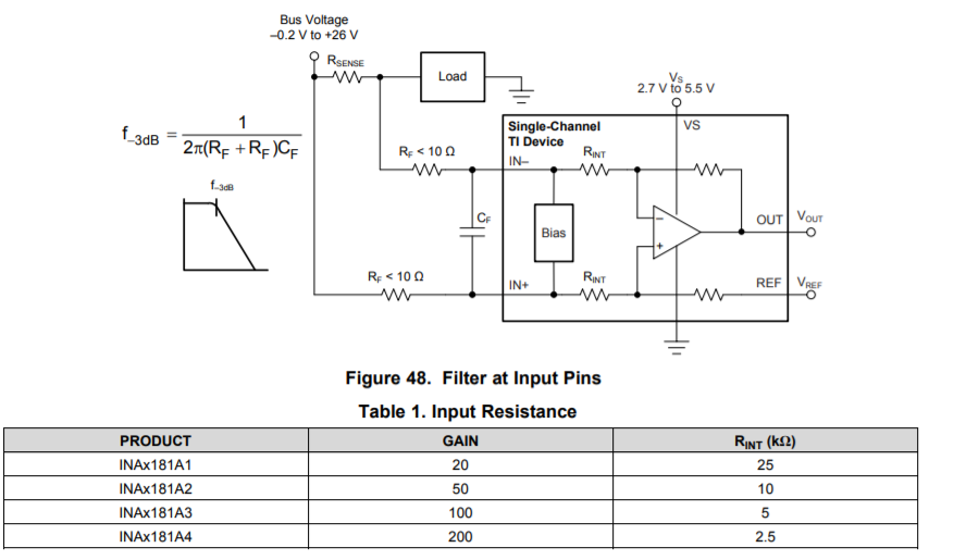
The customer have a question about the internal bias circuit shown in Figure 48.

What is the internal bias network? Is it a circuit like an attenuator for high common mode voltage?

Best Regards,

Naoki Aoyama

  • Hello Naoki,

    Thanks for your interest in our products and promoting them to your customers.  The internal bias circuit is used for sensing the common mode voltage supply.   Based upon whether the common mode voltage is higher or lower than the supply, this sense circuit will switch which supply is used for one of the internal op amps.  This allows the device to work with inputs that are well beyond the supply rail, something a typical simple amplifier cannot normally do.  You can observe the effect of this switching in the input bias current and quiescent current plots of the datasheet, shown below.

  • Hello Patrick,

    Thank you for your reply. I understood the internal bias network.
    The customer will use the INA181 with the common mode voltage is less than the supply.
    They are considering the input impedance.
    Can they consider the impedance without the internal bias circuit?

    Best Regards,
    Naoki Aoyama
  • Hello Naoki,

    I cannot say without further details.  What is your customer trying to do?  Why are they concerned about our input impedance or our bias circuit?

  • Hello Patrick,

    The customer will insert a LPF in front of the INA181.
    They are estimating a gain error.
    So they want to know the impedance.

    Regards,
    Naoki Aoyama
  • Hello Naoki,

    We sometimes provide this in the datasheet.  In this case, the figure and table (below) is found in the applications section.  There you can also find some equations on how to calculate the gain error.  One thing to keep in mind is that RINT has roughly a 30% tolerance, this because we trim our internal gain resistance to meet the desired ratio, as opposed to trimming individual resistors to a specific value.

  • Hello Patrick,

    I understood the input impedance.

    Thanks,
    Naoki Aoyama