This thread has been locked.

If you have a related question, please click the "Ask a related question" button in the top right corner. The newly created question will be automatically linked to this question.

OPA192: Gain error calculation.

Part Number: OPA192

Hello team,

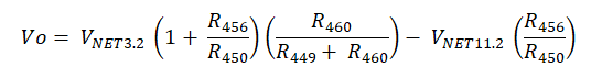
My customer intend to use OPA192 as current monitor as attached schematic (gain=200V/V), in this design case, they want to know about the gain error accuracy looks like, can you advise the way of gain error calculation?

Very appreciate.

Martin

OPA192 Gain Error Calculation.pptx

  • Hello Matin,

    The high-side current sense circuit using the OPA192 is simply a difference amplifier circuit. The open-loop gain (Aol) of the OPA192 is extremely high so at low frequency the gain error due to limited Aol will likely be negligible compared to the errors contributed by inexact resistor values.

    The gain equation for the circuit is:

    Take the 4 resistors and calculate their resistance extremes based on their 0.1 % tolerances i.e. for R449 and R450 that would be 1 kOhm +/- 1 Ohm, or 999 Ohms and 1001 Ohms. Repeat the calculation for the 200 kOhm R456 and R460.

    Your homework will be to test the equation with all the possible combinations of the resistors varied to their extreme values. You can set the equation up in Excel and that should save you some time doing the calculations. You may be able to deduce by inspection which combinations will yield the worst case gain error.

    One or more particular combinations of the resistor tolerances will yield the worst case gain error. The greatest deviation of the gain from the ideal gain is the one producing the highest gain error.

    Regards, Thomas

    Precision Amplifiers Applications Engineering

  • Hi Martin,

    Did this take care of your OPA192 gain error calculation question? If so, please close this e2e inquiry.

    Regards, Thomas
    Precision Amplifiers Applications Engineering