This thread has been locked.

If you have a related question, please click the "Ask a related question" button in the top right corner. The newly created question will be automatically linked to this question.

XTR117: Maximum loop load

Part Number: XTR117
Other Parts Discussed in Thread: OPA344

Hi,

I have exactly the same circuit described in the thread "XTR117: Interface a XTR117 with a Photo Transistor and a MCU".

In my design, the phototransistor is just part of the optocoupler CNX82A that I am using to decouple the XTR117 from the control circuit.

The problem is that the current driver does not work for loop load exceeding 250 ohm and the XTR117 datasheet does not report any limit, neither any derating curve depending on the load.

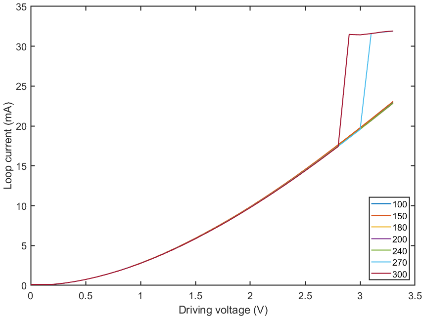
The results of my characterization are reported in the figure above.

At the current design stage, the control is not linear, but this was intended to be just a test and as you can see this is not my main concern.

I performed the same test under the following conditions but no improvement was detected

  • test under different power supply conditions up to 36V
  • test with different resistor values
  • test with different NPN BJT, N-MOS

As soon as the current output switch to the saturating value, no action on the input can restore the normal operation.

Are there some considerations that I am missing?

  • Hi Carlo,

    what is the maximum current through the output transistor of optocoupler? See the section "Minimum Output Current" of datasheet.

    And what do you mean by "driving voltage"?

    Kai
  • Hi Kai,

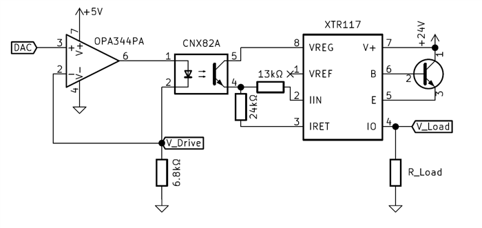
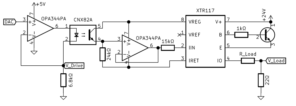
    For the test I used a Ni DAQ USB 6356 that drives an opamp current generator and acquires the voltage on the loop load. (see figure below)

    Therefore, the test result refer to the current  V_Load / R_Load againts the driving voltage.

    Unfortunately, it's very diffcult to characterize this device. The simple connection of the DAQ terminals at the input 2-3 of the XTR117, even given the extremely high input impedance, is enough to induce instability.

    Since no information is given about the maximum loop load, I'm curious to know if the XTR117 has some limitations or I am somehow involuntarily affecting the measurement..

  • Hi Carlo,

    From the XTR117 output point of view, the device can supply up to 32mA at its output. The maximum load resistor will be dependent on the loop supply+ or compliance voltage in the system. The XTR117 has a minimum power-supply voltage, VCOMPLIANCE, of +7.5 V between V+ and IO for proper operation. If the resistive load and/or resistive losses due to cable length cause the supply voltage to decrease below +7.5 V, the system will lose its ability to regulate the output current.

    However, in your schematic above, there should not be any issue with the compliance voltage, since your maximum load is 300 Ohms, Iout=24mA current and the supply is +24V; leaving a compliance voltage of ~16V.

    In the circuit above, when you have a load = 300 ohms, and the driving input voltage is ~2.75V; what is the voltage between pin5 (collector) and pin4 (emitter) of CNX82A? Any chance the CNX82A is going into saturation?

    Many Thanks,

    Luis

  • Hi Carlo,

    I agree with Luis. Will it help to replace the 13k resistor by a 25k resistor?

    Kai
  • Hi Luis and Kai,

    thanks for the suggestions. I tried replacing the 13k resistor with 24k but nothing changes.

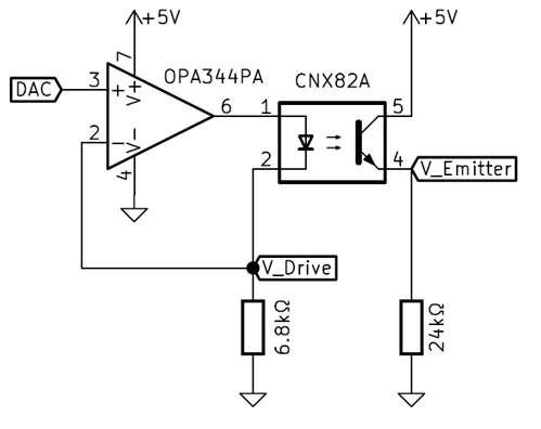
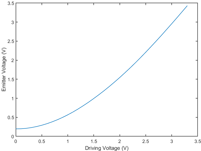
    I characterized the optocoupler separately from the rest of the circuit (see figure below) and it seems clear that is not going into saturation.

    I also made some modifications to the circuit:

    • replaced the Rin 13k resistor with 15k to limit the test current to the XTR117 linear range (0-25mA)
    • added an OPA344 buffer between pin 4 of CNX82A and pin 2 of XTR117 to avoid load effects (quiescent current is negligible)
    • added a shunt resistor close to the ground to further decouple the DAQ input from the XTR117
    • added a 1k resistor between pin 6 of XTR117 and the base of TIP41 (optional)

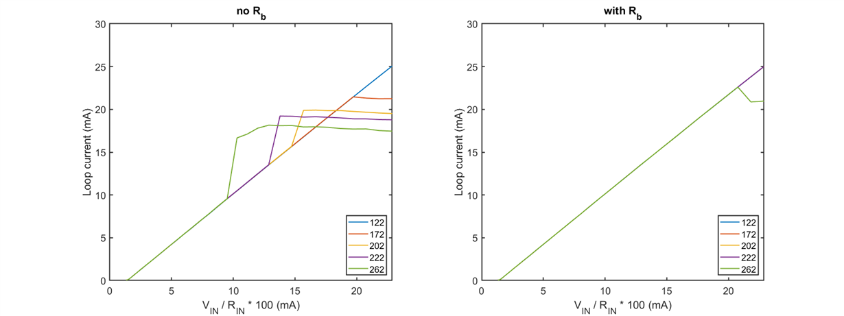
    I repeated the test with and without the 1k base resistor and plotted the results with respect to the current sourced to pin 2 of XTR117 multiplied by 100.

    A part from an offset and a gain error, I am generally unable to drive the XTR117 when the load approaches the 200 ohm, condition that is partially solved by introducing a base resistor.

    It seems to me that there are some stability issues that I'm not able to overcome and I've run out of ideas with the XTR117.

  • Hi Carlo,

    add a 10...100n cap between pin 7 and pin 4 of XTR117. Replace all components by fresh ones.

    If the circuit still doesn't work properly then, I would also remove the opto for a test and replace the opto transistor by a resistor in order to form a resistive voltage divider at the input of the right OPA344. Or mount a resistor directly from pin 8 to pin 2 of XTR117.

    Divide and conquer...

    Kai
  • Hi Kai,

    thanks for the help, I replaced the optocoupler with a simple potentiometer and....nothing changes, some results.

    But I finally solved the dilemma.

    The XTR117 clearly becomes unstable as the loop load increases and the only simple solution is a capacitor between pin 7 and 4 as you suggested.

    I must say that this capacitor should be explicitly advised on the datasheet because the XTR117 simply DOES NOT work without.

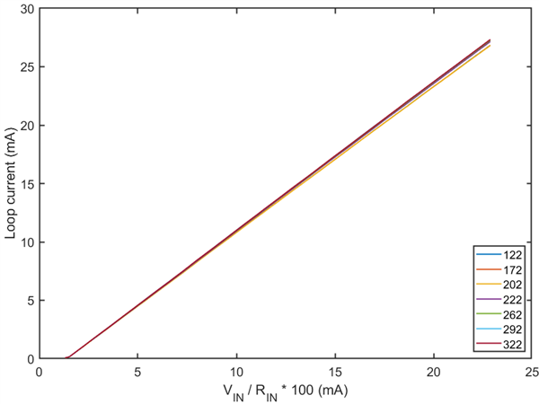
    In the following are the result I obtained adding a 100 nF capacitor.


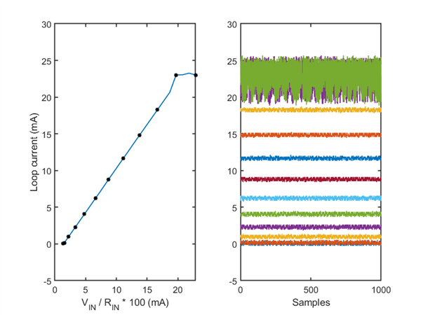
    But it is also interesting to see what actually happens without capacitor for a loop load of barely 150 ohm:

    The oscillation is apparent for the last two input values and it tends to manifest earlier as the loop load increases.

    I hope these results and conclusions might avoid to someone else the huge wastage of time I faced for a simple capacitor not specified on the datasheet

  • Hi Carlo,

    figure 1 "basic circuit connections" contains this 10n cap.

    I understand that you are upset. But please don't feel offended when I say that it's common practice to always mount a decoupling cap when the datasheet recommends one: If you see a decoupling cap in a datasheet, then read it as: "You must mount this decoupling cap! If you omit it, you will do it on your own risk."

    Kai
  • Dear Kai,

    I appreciated the hints you gave me to find a solution, less to be taught a lesson on how to read a datasheet.

    I'm not upset, I was just openly wondering how is it possible that a component on which depends the stability of the entire circuit is not discussed at all, not even a line in datasheet to provide a suggested range, not even a line to say that it affects the stability.

    Furthermore, the figure you refer is not so generic, it describes a basic application for bridge sensing. Whereas in the complete solution in Fig 5 it is not present.

    The capacitor should have, in my opinion, at least reported in the figure of pag 1 if so important.

    Or maybe I will have to learn to silently replicate a design without wondering why..

  • Hi Carlo,

    I apologize. I didn't want to offend you.

    Yes, you are right. The decoupling cap should be shown in each figure of datasheet.

    Kai