This thread has been locked.

If you have a related question, please click the "Ask a related question" button in the top right corner. The newly created question will be automatically linked to this question.

LM393: input to output delay time

Part Number: LM393

Hi,

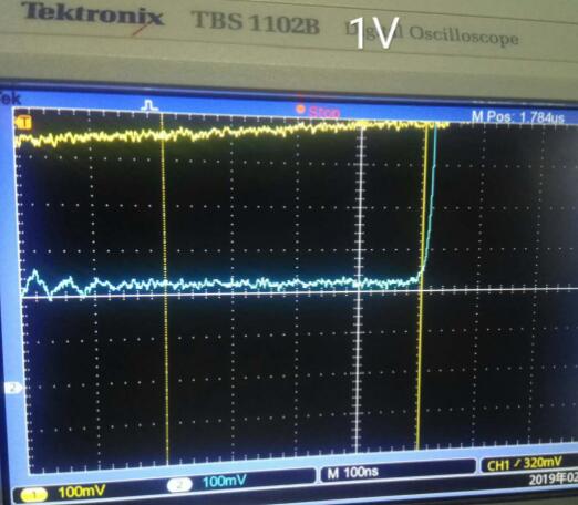
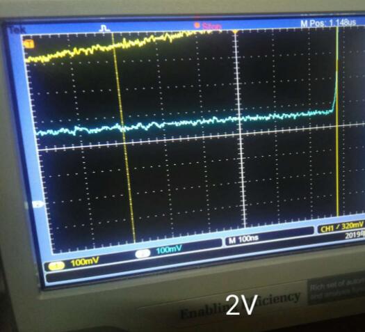
The input is a 40KHz sine wave. I found with input peak-to-peak amplitude rising from 1v to 2v, the input to output delay time becomes larger.

In the datasheet, I found the information of overdrive voltage which is defined in mV level. The behavior of overdrive voltage and response time is opposite to input amplitude and delay time. I don't know if response time/delay time and overdrive voltage/input amplitude are the same thing.

Thanks.

8.2.2.2 Minimum Overdrive Voltage
Overdrive Voltage is the differential voltage produced between the positive and negative inputs of the comparator
over the offset voltage (VIO). To make an accurate comparison the Overdrive Voltage (VOD) should be higher
than the input offset voltage (VIO). Overdrive voltage can also determine the response time of the comparator,
with the response time decreasing with increasing overdrive. Figure 8 and Figure 9 show positive and negative
response times with respect to overdrive voltage.

  • Hello Di,

    Can you please post your schematic and your scope photos? There are many things that can change the apparent propagation delay. Also make sure you are not violating the input voltage range, as this can cause the prop delay to increase.

    The definition of propagation delay is the time from the CENTER of the input waveform to the CENTER of the output waveform. If you are just using the scopes measurement function, there can be errors if the triggering levels are not correct and/or there are distortions/slewing in the waveforms.
  • Thank you.

    Vcc is 3.3V through a diode, so Vcc is about 3.0V. CH1 is input sine wave and CH2 is output. The trigger level is 552mV. I measured the time duration from input(CH1) reaches 552mV to output(CH2) starts to rise from 0V. When input is 1 Vpk-pk sine wave(40kHz), this time duration is 404ns. When input is 2 Vpk-pk, it is 580ns.

    I don't understand the definition of minimum overdrive voltage and response time in Figure 8 of datasheet. 

    Could you pls explain why the time is larger with input amplitude increases? 

  • Hi Di,

    What is the 1-2Vpp centered around? Can you zoom out so we can see the entire waveform, referenced to ground. IOW, what is the "high" and "low" voltage in respect to ground.

    At 3V, the maximum input voltage is 1.5V (1V over temperature) At the higher 2Vpp level, part of your waveform may be going out of input range and, while the output will still be correct, there will be an increase in prop delay. If any portion goes well below ground, this can also cause delays.

    Overdrive is the amount of input signal OVER the reference voltage - NOT the total p-p input voltage. So if you had a reference voltage of 1.000V, and the input signal went from 500mV to 1.05V, then the "overdrive" voltage is 50mV.
  • Di
    we have not seen a response in a while, so we are closing this post. If you need further support, please hit reply and this will reopen the thread.
    Chuck