This thread has been locked.

If you have a related question, please click the "Ask a related question" button in the top right corner. The newly created question will be automatically linked to this question.

OPA2277: Matched Pair of Op-Amps.

Part Number: OPA2277
Other Parts Discussed in Thread: XTR106

Presently we are using OPA2277 in one of our application. We would like to know how to order / identify matched pair of Op-Amp so that the output of both the Op-Amps are closely matched to each other. Presently in our testing we find that there is upto 28% difference in the outputs of Op-Amps of different lots. We have the following results displayed as ADC output.

OpAmp 1 Channel A : Average ADC count is 16904 ; Channel B Average ADC count is 15259; here the difference is 1645 [9.7 %] which is acceptable.

For the same sensor with different Op-Amp

OpAmp 2  Channel A : Average ADC count is 11028; Channel B Average ADC count is 15368; here the difference is -4340 [-28.2 %] which is un-acceptable.

Ideally, we would like to have same output for same sensor.

Kindly advice.

  • Hi Sudharsan,

    this cannot be answered without seeing the circuit. Can you show us a schematic?

    Kai
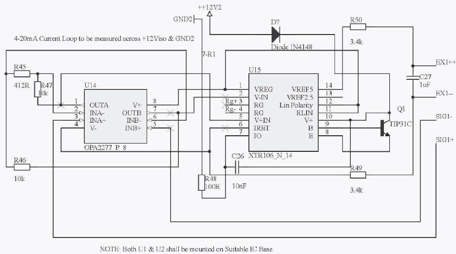
  • This is derived from the figure 05 of the XTR106 datasheet; recommended for low bridge impedance.

  • There are 2 channels for load cell and 2 channels of the XTR106 scheme. We want to eliminate the usage of gain setting trim pots since they may affect performance at customer site if improperly tuned.
  • Hi Sudharsan,

    what bridge is connected to the OPA2277 during your measurements? What RG have you connected to the XTR106? What voltages do the ADC counts mean? And where exactly are they measured?

    By the way, I would remove C27 and provide an input filtering instead, like shown in figure 1 or figure 6 of datasheet.

    Kai

  • Kai has a valid point. Based on the internal architecture of the XTR106 you cannot use it without an RG. Without RG there will be erratic readings. Also there is no product offering for matched op amp in a dual package.
  • Bridge impedance is 350 Ohm. 3 mV/V sensitve . Rg is 87 Ohms, since its non standard value of resistor we have 2 parallel 174 which is shown outside the scheme. we expect 65535 counts for input max load of the load cell. [20mA]

    Figure 1 capacitor is Recommended for bridge impedances > 10kΩ &
    Regarding the filters as on figure 6, Im not clear how is it going to impact the ADC counts that have an OFFSET drift.
  • Hi Sudharsan,

    section "Radio Frequency Interfence" and figure 6 recommends input filtering. If unfiltered HF interference is present at the inputs, the circuit might not work properly. This is not only true for the inputs of XTR106 but also for the inputs of your OPA2277. So, if you want to filter the bridge, then it's of main interest to have this filtering at the inputs of OPA2277. An instable OPA2277 could indeed be responsible for your measuring errors.

    But because of now knowing your XTR106 gain, I think that it has to do with the input offset voltage of OPA2277. 50µV input offset voltage results in a change of XTR106's output current of 50µV x 50 x 40 / 87 = 1.1mA.

    Kai