This thread has been locked.

If you have a related question, please click the "Ask a related question" button in the top right corner. The newly created question will be automatically linked to this question.

INA225: Current sensing on high power bldc driver

Part Number: INA225
Other Parts Discussed in Thread: LM339

Hi,

I'm trying to build a bldc controler able to drive a 15kW motor...

I have trouble to get a coherant measure of current in each phase... I fact i am developping the controller board using a pre-existing powerboard to speed-up the task. But  this power board has only shunt resistors on each phase but no common shunt... and it is realy low resistors  (i mean pcb trace) about 50 micro-ohms...

I'm trying to get the rotor position using the inductance variation method, shortly I drive High to phase and the third is driven low and then reverse the phases...

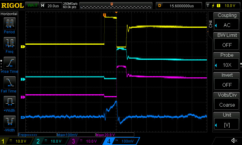
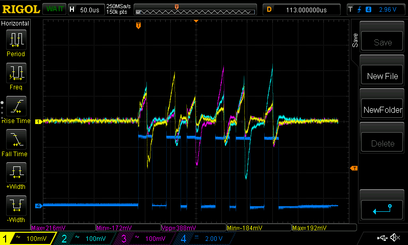
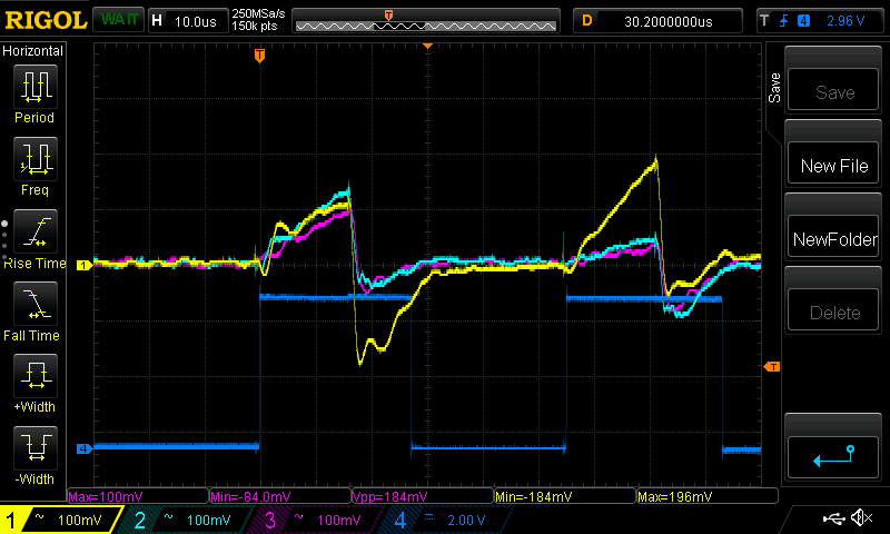
Here you can find some pictures of waveform :

First pulse U and V are pushed to 30V and W is driven to 0V then in the secon pulse W is driver high end U and V are diven low...

The current is taken from the shunt resistor to an INA225 with G=100 and a ref voltage around 0.5V.

Currents : Yellow = phase U, blue = phase V and pink = phase W...

Is someone can explain me why in the first pulse I catch a current in every shunt ? I mean why the yelow one is following the other ones ??

Mosfet is off and I've done many simulations and I can't understand why the op amp amplify this ghost current...

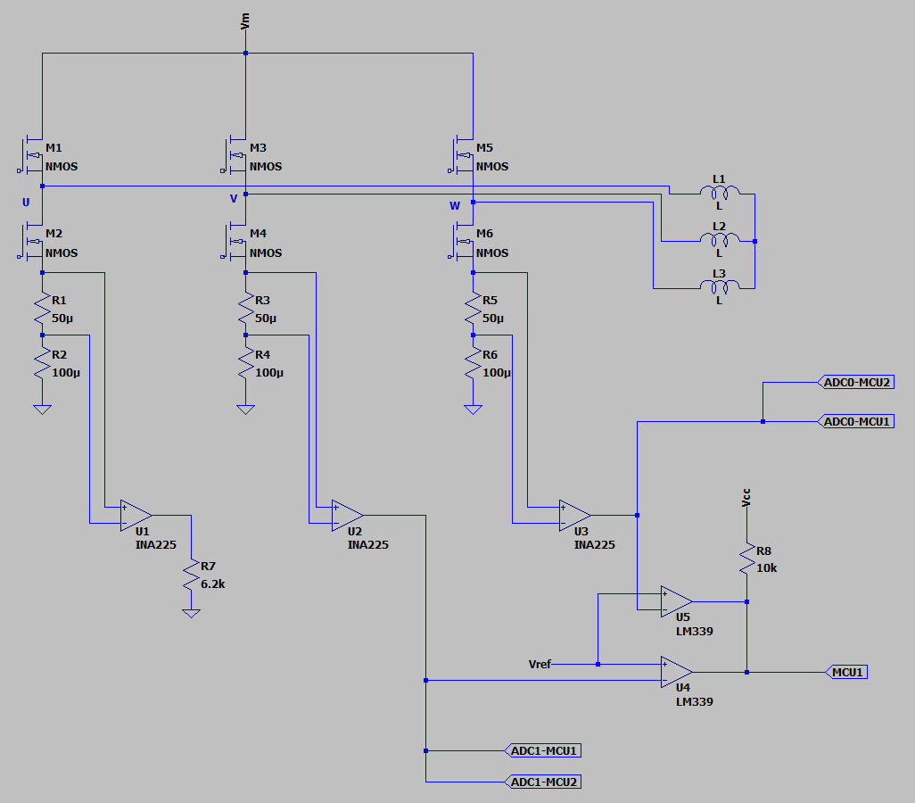
Here is a schematic of one simulation with layout resistance of the bridge

I can' t explain what I see on the scope...

I'm pretty sure this current does not exist !

  • Hello Raphael,

    Thanks for considering to use Texas Instruments.  To determine what is going on I need a few more details.  Are you using a special motor driver IC for driving your gates or are you using a microcontroller to drive your gates?  If you are using the a microcontroller, did you write the software, or did you leverage pre-existing code?  If it is pre-existing and publicly available, can you tell me your source?  If I understand correctly you said this is predominantly a problem with the first pulse.  However, it looks like in figure 1 that this occurs every other pulse.  Perhaps, you have more gates turning on than expected.  Can you monitor the gates to M2, M3, and M6 simultaneously?

  • Hello Patrick,

    Mosfets are driven with IRS21864 and an AVR mcu. Software was writen by me, no library at all it is pure assembly.

    Phases are driven like this :

    UH VL WL  

    UL VH WH

    UL VL WH  

    UH VH WL

    UL VH WL 

    UH VL WH

    Yes the problem is present on pulses 1 3 and 5, when two Low side mosfets are switched on.

    I dont think there is any unwanted Mosfet on, it will lead to cross conduction and peack current should be a lot higher.

    Code is very simple, for the first pulse :

    	ldi		r16,0x06		;
    	out		PORTE,r16		;	VL & WL
    	ldi		r16,0x20
    	out		PORTB,r16		;	UH
    

    High side is mapped on PORTB bits 5, 6, 7

    and low side on PORTE bits 0, 1, 2

    respectively U, V and W.

    Thank you. 

  • Hello Raphael,

    I understand your stance that an unwanted mosfet is likely not on, but can we still check it? Just would like to completely remove that from the list of possibilities early on.

    Aside from that can you provide an additional scope shot monitoring U, V, W and a single Vsense voltage.

    From looking at your sequence, it is a bit different from sequences I am used to seeing. Is there a particular reason you are using this sequence pattern? The one I am familiar with looks like:
    UH VL WFloat
    UH VFloat WL
    UFloat VH WL
    UL VH WFLoat
    UL VFloat WH
    UFloat VL WH
  • Hello Patrick,


    Ch1 = U phase

    Ch2 = V phase

    Ch3 = W phase

    Ch4 = Vsense on U (picture 1), V (picture 2) and W (picture 3)

    The sequence is not a regular one entended to drive the motor but only to test inductance values in different rotor positions.

    Best Regards,

    Raphael Reynard.

  • Hello Raphael,

    That defies what we would expect. However, I do have a possible theory. The outputs might be coupling onto each other. From your graph it appears as though 2 INA225 outputs have the same initial droop and overshoot with the rise, while the other appears to have a more smooth RC charge rise characteristic. Possibly one of the signals is filtering through onto the output you expect to be low. So to test this theory, I first would like to cut the connection between the source and shunt on the low-side that is expected to be off. This should guarantee that nothing is passing through that shunt. If the output is still unexpectedly high, reconnect that source and shunt and then cut the output trace. Probe at the output pin and see if it still rises when it is expected to be low.
  • Hey Raphael,

    Were you able to run any of the tests I suggested above?
  • Hello Patrick.

    No I didn't....

    In fact cutting a trace is not an option because it is inner layer of the pcb. But i can unsolder mosfets to get teh same result. It is a bit tricky because every swhitch is build with 6 mosfets and they are smd so I need to heat up a large part of the pcb.

    We are going to buy a heating plate to ease soldering and unsoldering of this kind of thing.

    At this time I've canceled this way of start-up sequence and go back to motor-specific ramp.

    But  I need to be confident with my current measure, so I need to understand what's happening.

    In fact the schematic i've posted is what I suppose to be. The power-board is not our own, I use it to speed-up development. The power-board carry only mosfets and capacitors. I don't realy know how are the inners layers. I have done a virtual pcb, folowing the real one for external layers and  guessing how are the inner layers.

    All resistance was measured at DC with 7 amps and HP 3468A multimeter.

    Here is a picture shownig how I think the inner layer is.

    Green arrows are the current form low side source to main capacitor.

    In the blue circle you can see the start and the end of shunt resistor.

    You talk about coupling, and I agree with you, especialy when I look at the negative current in the first oscillo sceenshot that reflect a bit on the next sceenshot and disapear on the last, reducing when the distance grow. But this effect is very strong, all the peaks are very close.

    Thank you for your help.

    Best regards.

    Raphael Reynard.

  • Hello Raphael,

    I dont see an obvious issue with that board. However, I will discuss this with my colleagues and see if they may have any thoughts on what could be wrong.

    As for your INA225 outputs, do each of these feed directly to a different adc pin on a microcontroller or do you feed them through some sort of mux. If there is a mux, perhaps there is crosstalk that is allowing the signal to couple. As it is difficult to cut your output trace, could you alternatively lift pin 4 of the INA225 off the board and attach a wire to probe this output pin? If you can confirm that the output does not change after this, then we can confirm the behavior is not a result of some downstream circuitry.
  • Hello Patrick,

    No extra  mux but adc input of two mcu and it is muxed inside mcu. And ouput of INA225 feed a comparator (LM339) to...

    I've disconnected output on U phase and loaded it with 6.2K to ground and here is a scope screenshot :


    Ch1 is U with op amp disconnected from mcu/comparator

    Ch2 and Ch3 are V and W (with op amp connected to mcu/comparator).

    First pulse : UL VH WH

    second pulse : UH VL WL

    Thank you.

    Best regards

    Raphael Reynard


  • Hello Raphael,

    So if I understand correctly, your bridge circuit for U looks like the figure below?  If so, this is not expected behavior from our device.  To determine if this is an issue with our device or with the system,  I have two additional tests you can perform.  One would be to take a high-side measurement.  If in fact the current is real, I think we should see the high-side current sum up to the current passing through all three of the low-side current shunt monitors.  In this test I would also recommend removing the 6.2kohm resistor.  The other test you can perform would be changing the shunt resistor on the U leg.  If you change the shunt to 250uohm, we should see the output amplitude from the INA225 get 5x larger.  This would also indicate if excess unexpected current is passing through the shunt.

  • Hello Patrick

    No !!

    Sorry I didn't explained enough...

    It's the op amp (the one that sense U phase)  output that was disconnected from the mcu/comparator inputs and connected to ground with a 6.2k resistor.

    U, V and W phases are still connected to motor.

    best regards.

    Raphael Reynard.

  • Hello Patrick

    No !!

    Sorry I didn't explained enough...

    It's the op amp (the one that sense U phase)  output that was disconnected from the mcu/comparator inputs and connected to ground with a 6.2k resistor.

    U, V and W phases are still connected to motor.

    Best regards.

    Raphael Reynard.

  • Hey Raphael,

    Thanks for the clarification. Based off that, we do think that there is current actually crossing through R1 when it should not. To determine where it is coming from one test would be to disconnect node U from L1, this will tell us if for current is feeding through from the inductor. The other test you could also try would be to desolder R1 and probe for a short to the high-side of R1. For this I would first check if the high-side of R1 is shorted to the high-side of R3 and R5, then to V and W, then the output of U2 and U3. I would check these resistance as well if possible.