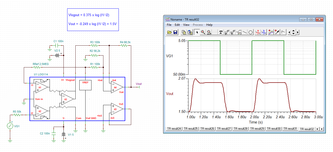
This thread has been locked.

If you have a related question, please click the "Ask a related question" button in the top right corner. The newly created question will be automatically linked to this question.

LOG114: Step response performance greatly differs from datasheet

Part Number: LOG114

Hi!

I've got a problem with LOG114, it does not match submicrosecond step response time as it should according to datasheet. My scheme has +-5V dual supply, I2=2,5uA and I am getting submicrosecond responce times only in area of at list 1-10mA input currents. If I try 1uA to 100uA or 1uA to 1ma or 100uA to 1ma square pulse it shows response times (10 - 90% rise time) greater than 1,5 - 3us. Datasheet states that response time should be less than 0,15us. Is there any resonable explanation for that? Tried already replacing IC with another LOG114, got same results.

  • Hi Andrey,

    how do you generate the input current step changes? And where do you measure the step response? Are all measuring conditions as specified in the datasheet (VCM=GND, RVLOGOUT=10k, IREF=1µA)?

    Kai
  • Current pulses were generated by avalanche photodiode coupled with fast light source, and also by connecting input to pulse generator via resitor. Results were the same. VCM = GND, IREF=2.5uA, output resistance not exactly applicable, I tried buffering output with op amp and also connecting standart 10Mohm oscilloscope probe directly to Vout. Result also remained the same.
  • Hi Andrey,

    the simulations show that it should work:

    andrey.TSC

    andrey1.TSC

    Could it have to do with your setup? Is there any cabling involved or stray capacitance? Is the circuit breadboard mounted? Remember that the LOG114 is high-speed logarithmic amplifier. You should use HF mounting and measuring techniques. Also, a 1:1 scope probe can show a huge capacitive load to the outputs of LOG114. I would use a 10:1 scope probe. And don't directly touch the outputs of LOG114 with the scope probe. Insert a 47...100R isolation resistor which you mount directly at the output pin of LOG114.

    Kai

  • Thanks, Kai!
    Althow I am aware of the secret world of probes, your post made me reconsider previos tests and trials. Today I looked again at the PCBs with mounted LOG114 and tried touching with the probe throwhole connected directly to Vlogout on board with buffer amplifier. And I found out that the signal just after log114 is okay, troubles were introduced by (or after) ad8031(not sure yet why). And on another old pcb, which I used for testing without phodiode, was mounted, effectivly, a low pass filter between Vlogout and board's output pin. I have not discovered it at first. So now I am going to replace op amp in voltage follower and enjoy submicrosecond performance of my new pyrometer.
    As for "And don't directly touch the outputs of LOG114 with the scope probe. Insert a 47...100R isolation resistor which you mount directly at the output pin of LOG114." I am not sure why I should not have touched it directly? I almost always use probes in 1:10 mode and they have input capacitance about 10p, it should not be considerable load as long we are not talking about hundreds of Mhz. Static charge also can't not be an issue...
  • Hi Andrey,

    happy to hear that you could solve the issue!

    Yes, with a 10:1 scope probe of only 10pF probe capacitance it's rather difficult to make an OPAmp become unstable. But this is only true, if the OPAmp is designed properly and has enough phase margin. An unstable OPAmp circuit, on the other hand, can immediately begin to oscillate when its output is touched by anything. I have seen this many times. That's why I always recommend to use an isolation resistor at the output of OPAmp when any difficulties arise.

    Kai