This thread has been locked.

If you have a related question, please click the "Ask a related question" button in the top right corner. The newly created question will be automatically linked to this question.

INA240: unexpected spike in the output

Part Number: INA240


Hi team,

Customer is using INA240A2 for low side current measurement. The current to be measured has a frequency of 15kHz, which is the current of the lower bridge arm of a half-bridge DC motor driver circuit, and may be up to 300A peak. The shunt resistor is 16mOhm.

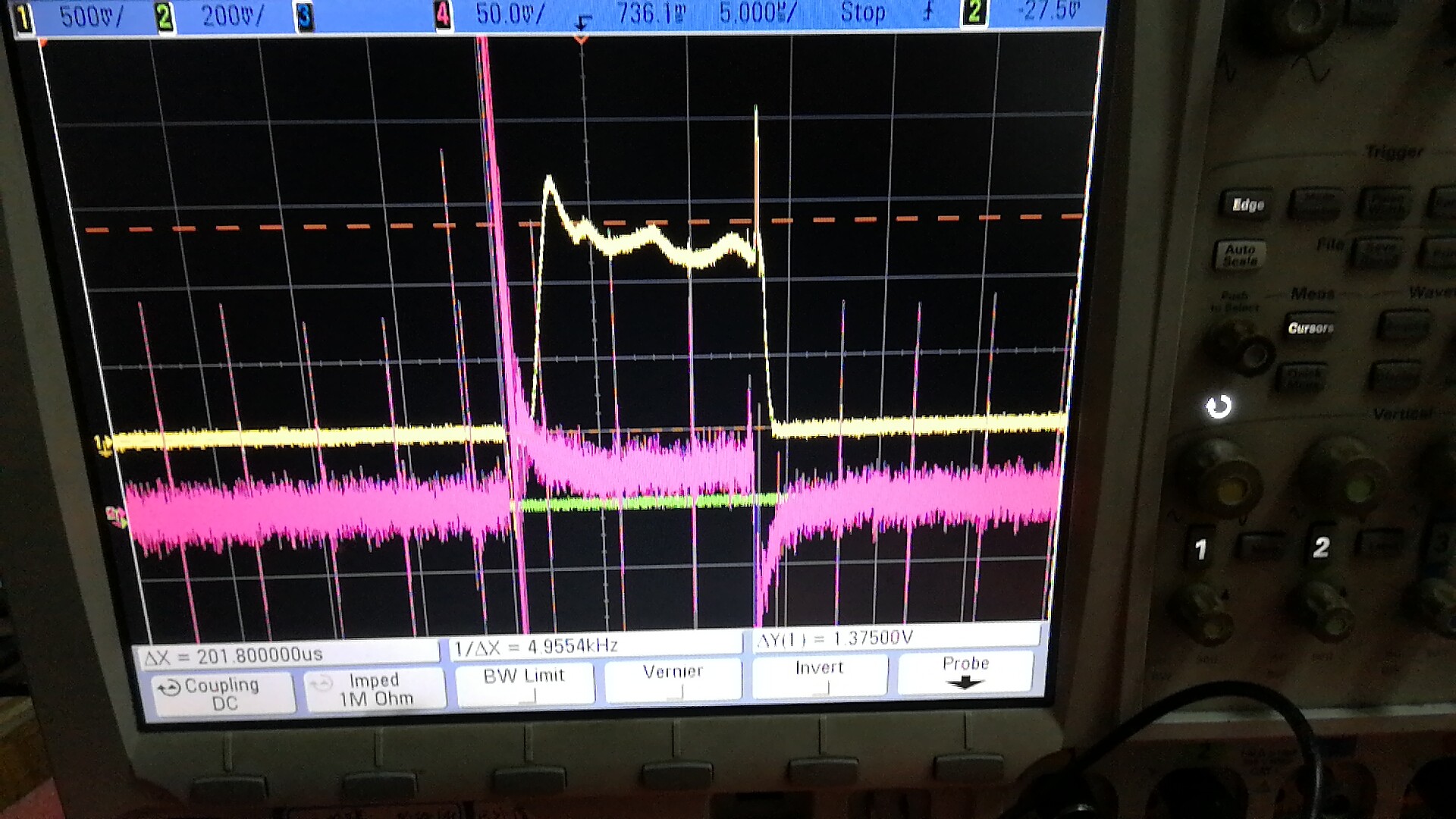
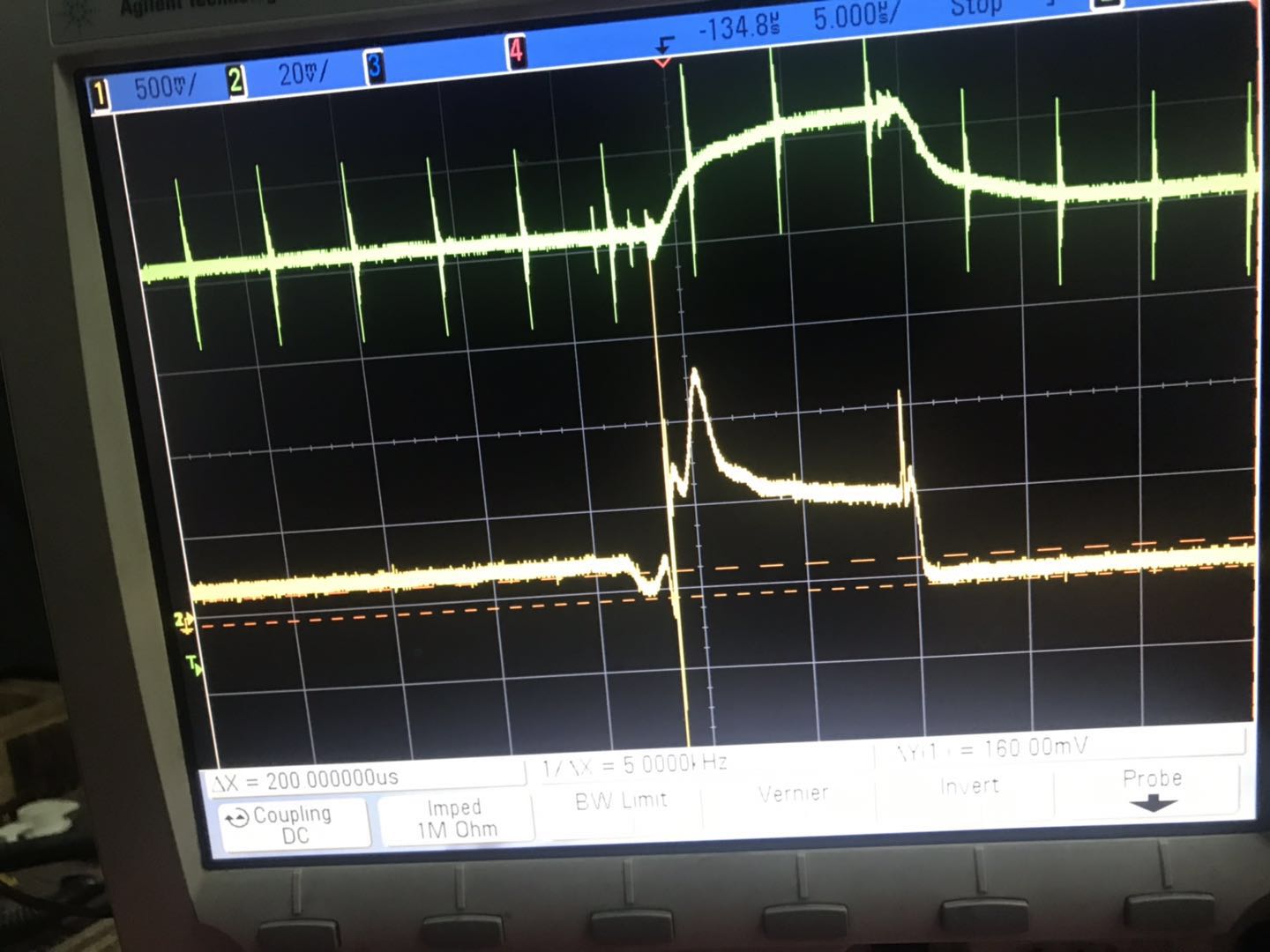
The measured waveform as below:

Red is the differential input of the shunt resistor.

Yellow is the output voltage of INA240.

We can see a spike in the output right before the dropping edge. I'm wondering what may cause this spike? 

Thanks!

George

  • Hi George,

    can't see the waveform.

    Can you post it again? Click the "Insert Code, Attach Files and more..." button. Then click the "Insert File" button in the header.

    Kai
  • Hi George,

    You may also want to check if the spike coincides with one of the edges of a PWM waveform, sometimes from another channel. Such a spike is due to cross talk and in general composed of a series of high frequency pulses and should settle quickly relative to your switching frequency. If not, then there might be something else going on.

    Regards, Guang

  • Hi Guang,
    Thanks for your reply.
    If the spike does come from PWM, any suggestion to remove it?
  • Hi George,

    What is the INA240 output feeding into, an ADC, a comparator or something else? How is the information being used? How are the spikes affecting the system functionality currently? Once we know what we’re dealing with and what the goal is, then ii might be possible to adopt certain measures to reduce their side effects.  

    Regards, Guang

  • Hi Guang,

    Thank you very much for your suggestion, I will consider those aspects and see what can be done to improve.

    Meanwhile, customer had tried to use INA240A3 to increase amplification to 100V/V, the spike seems to increase a lot, as below:

    I'm thinking it is because the parasitic inductance at the input caused a large reverse voltage when the sharp drop came, thus generated a large amplified spike on the output.

    I would like to hear your comments on this, thank you!

    George 

  • Hi George,

    I think you’re correct, it is almost certain that the larger spikes are due to shunt inductance, especially when they seem to be amplified by the higher gain. And the shunt voltage (purple) seems to show it as well. Unfortunately shunt manufactures tend to be vague on the resistor parasitic inductance. Often it is specified in a wide range if it is mentioned at all.

    A capacitor across the input pins might help alleviate the problem.

    Regards, Guang

  • Hi Guang,
    Thanks!
    Do you mean a capacitor in parallel with the shunt resistor? Since the current to be measured has a frequency of 15kHz, I'm afraid a parallel capacitor may change the impedance and thus affect the accuracy, am I right?
    George
  • Hi George,

    There is enough separation between the switching frequency and that of the over/under shoots. The cap impedance should look like an open relative to the shunt resistance at low frequency and short relative to the parasitic inductance at high frequency.

    Regards, Guang

  • Hi George,

    It's been several days since your last post, so it seems like your issue has been resolved. If you need more help, please reply to re-open the thread or start a new thread with a new question. Thanks!

    Best regards,

    Ian Williams
    Applications Manager
    Current & Magnetic Sensing
  • Hi Guang,

    Sorry for late reply, the customer didn't do further test until yesterday.

    I recommended the customer to use the EVM of INA240A3 and flywired to their system. Added the input filter with 50Ohm resistor and 100nF capacitor, the result didn't seem any better:

    I noticed in the datasheet of INA240 that in the application curve a similar spike also appears at the similar position, why is this happening? any other suggestions on how to better measure this current? Thanks!

    George

  • Hi George,

    would you like to check this filtering?

    e2e.ti.com/.../2834131

    C3 in the schematic should be 10...100nF, though.

    Kai

  • Hi George,

    Because this is a low side current sensing configuration, the glitches are mostly due to coupling and parasitic inductance of the shunt. These spikes can be reduced but will not be completely eliminated. Therefore a realistic goal is to reduce the spikes so that no false alarms are triggered. These spikes also fall within the settling time period. Measurements shouldn’t take place in first 5uS or so.

    A cap across the input pins should help in reducing the amplitude of the spikes caused by shunt inductance. When fly-wiring the EVM, please remove the TVS diodes because they are not useful here, instead they can potentially make settling worse.

    Regards, Guang