This thread has been locked.

If you have a related question, please click the "Ask a related question" button in the top right corner. The newly created question will be automatically linked to this question.

Howland Current Pump Feedback capacitor size determination

Part Number: OPA551
Other Parts Discussed in Thread: TINA-TI

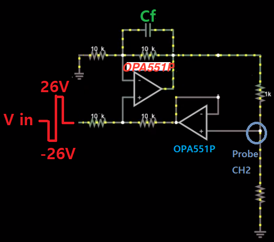
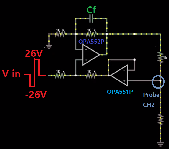
I use 2 OPA552P and one OPA551P. One OPA552P is configured as a non-inverting amplifier.

One OPA552P and one OPA551P is used for creating the improved Howland Current Pump.

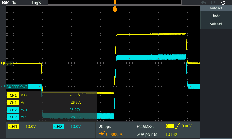
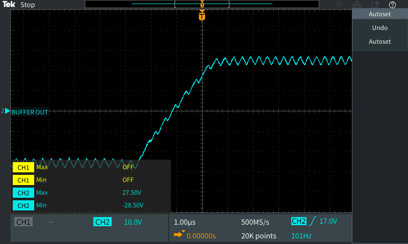
A 100 Hz periodic signal is fed to the Op Amp.

If I don't add a capacitor, the output voltage from the node is unstable like this. An amplitude of 2V of the sine wave is discovered.

But surprisingly, if I connect my Tektronix TPP0100 probe (1 MΩ/13 pF) to OPA552P's (-) input, the load's output voltage becomes stable.

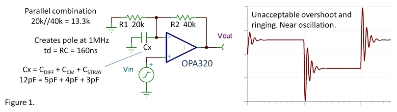
I tried 5 pF, 10 pF as a feedback capacitor, but this cannot make the output voltage stable.

How should I determine the feedback capacitor's size? I hope someone could explain this behavior when a probe is connected.

  • Hello David,

    If you are driving a resistive load with the Improved Howland Current pump I would expect it be stable using most operational amplifiers. However, I do see one problem with your circuit that is likely resulting in the instability.

    The OPA552P is not a unity gain stable operational amplifier and is specified for applications with gains of 5 V/V and greater. In those higher gains it should be stable, but likely isn't in your current pump circuit where the noise gain is only 2 V/V.

    I suggest replacing the OPA552P with an OPA551P and seeing if the circuit is then stable. I realize that you have wide bandwidth, higher slew requirements, but if the circuit stabilizes that will point to the problem.

    Regards, Thomas
    Precision Amplifiers Applications Engineering
  • Thomas Kuehl said:
    I suggest replacing the OPA552P with an OPA551P and seeing if the circuit is then stable. I realize that you have wide bandwidth, higher slew requirements, but if the circuit stabilizes that will point to the problem.

    Hi, Tomas. You mean change it like this; installing two OPA551P?

    BTW, my input voltage signal is a periodic positive/negative pulse(Amplitude ranges to 3V ~ 26V, frequency ranges to 5Hz ~ 10,000 Hz).

    Also, back to the feedback capactior question,  what size of capacitor should I install and how is the size calculated?

  • Hi David,

    Yes, you would replace the OPA552P with the OPA551 as you have drawn the circuit above.

    Cf would have a small capacitance value. Its primary function in this circuit would be to compensate for the OPA551P inverting input capacitance, and any stray capacitance from the pin to the surrounding PC board traces. Since the input and feedback resistors are both 10 kohm, Cf would be set to the sum of that pin's input and stray capacitances. I expect that the capacitor could be something around 10 pF for starters.

    If you find that the load something has reactance and addition to resistance, stability and compensation can become a much more complex issue and exercise. That doesn't mean it can't be compensated; it just requires an in-depth stability analysis.

    Regards, Thomas
    Precision Amplifiers Applications Engineering
  • Thanks, Thomas. Just like you've recommended, the unstable output is now solved. I really appreciate it!

    Although you've solved this, can I ask your technical terms, please?

    Thomas Kuehl said:
    Cf would have a small capacitance value. Its primary function in this circuit would be to compensate for the OPA551P inverting input capacitance, and any stray capacitance from the pin to the surrounding PC board traces

    0.I thought adding a feedback capacitor was to solve this overshoot/ringing problem from the output, just like this picture below.

    Or is the feedback capacitor has a different purpose?

    1. What do you mean by "compensating for the inverting input capacitance/stray capacitance?" Like lowering the inverting input capacitance/stray capacitance?

    Thomas Kuehl said:
    I expect that the capacitor could be something around 10 pF for starters.

    2. How did you calculate that? Did you use the TINA-TI SPICE-based analog simulation program to calculate this? Or is there any theory for this?

    Thomas Kuehl said:
    it just requires an in-depth stability analysis.

    3. Does the  TINA-TI support this "in-depth" stability analysis?

  • Hi David,

    Please see my answers to your questions.

    1. What do you mean by "compensating for the inverting input capacitance/stray capacitance?" Like lowering the inverting input capacitance/stray capacitance? - I expect that the capacitor could be something around 10 pF for starters.

    The feedback resistance in conjunction with the total capacitance at the inverting input, creates a pole in the feedback loop. That adds delay, or phase shift, in the loop and the phase margin is degraded as a result. If the phase shift becomes too much and the phase margin approaches 0 degrees, the feedback becomes positive and the amplifier can oscillate.

    To compensate for the phase shift caused by the feedback resistor and input capacitance, a capacitance can be added in parallel with the resistor. Since both the input resistor and feedback resistor are 10 K, the added feedback capacitance needed to approximate the input capacitance. This essentially creates what is called a Lead-Lag network. The phase shift introduced by the feedback resistor and input capacitance is negated by an opposite phase shift provided by the added feedback capacitor and input resistor.

    2. How did you calculate that? Did you use the TINA-TI SPICE-based analog simulation program to calculate this? Or is there any theory for this? - it just requires an in-depth stability analysis.

    I didn't do any circuit simulation to establish the 10 pF feedback capacitor value. I estimated the total input capacitance to be about 10 pF based on the OPA551 common-mode and differential capacitance, and a few picofarads of board capacitance.

    3. Does the TINA-TI support this "in-depth" stability analysis?

    TINA-TI Spice is a powerful tool that can be readily applied in a stability analysis. We use it all the time for such analyses. The TI Precision Labs - Op amp series, in section 10, provides a lot of useful information about Op amp stability and how to address it. I suggest reviewing the section. It shows examples how TINA-TI is used as the basis for the stability analysis.

    You can find the TI Precision Labs - Op Amps: Stability information here:

    training.ti.com/ti-precision-labs-op-amps

    Regards, Thomas
    Precision Amplifiers Applications Engineering