This thread has been locked.

If you have a related question, please click the "Ask a related question" button in the top right corner. The newly created question will be automatically linked to this question.

TINA/Spice/INA188: Issue when simulating INA188 - the part distorts the INPUT signal

Part Number: INA188
Other Parts Discussed in Thread: TINA-TI, , INA826, BUF634

Tool/software: TINA-TI or Spice Models

Hi,

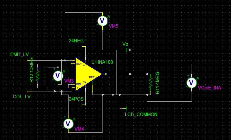
I am simulating the INA188 using the TINA-TI model that I have downloaded from its web page (this part is not available in TINA-TI included parts).

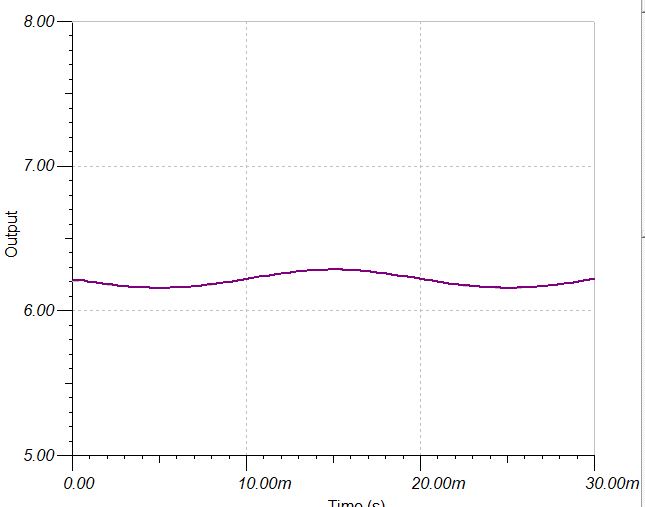
It simulates fine standalone, but when I include it in a more complex circuit, it seems that the INA188 inputs cause a disitrortion of the input signals.

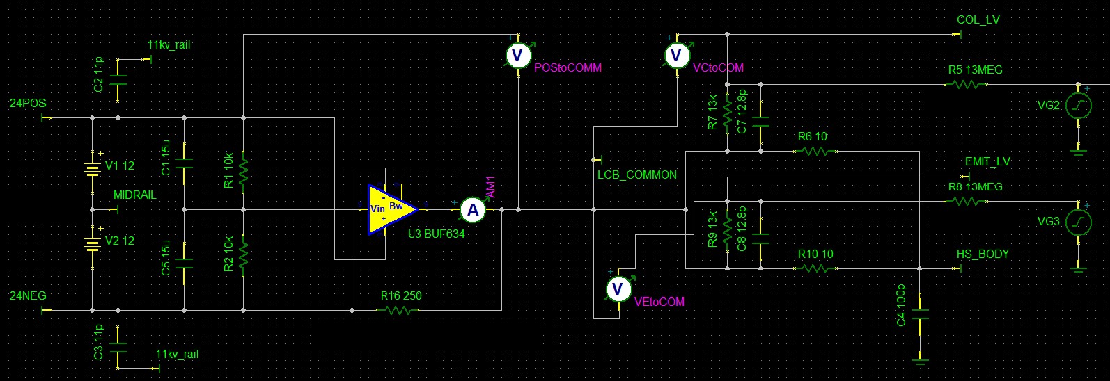
In this circuit, the INA188 inputs are fed from a high voltage (high impedance - 13Mohm) differential divider. 

When I change the INA188 to a simpler TINA model (e.g. INA826 which is included within TINA-TI) - I dont see this issue.

I can see that the INA188 is far more complex, but I wouldn't expect this input distortion behavior, since its input impedance is 100Gohm.

Please advise.

Thanks

Uri

  • Hi Uri,

    Could you provide a schematic and a screenshot of the distortion you are seeing? This will aid us in troubleshooting. 

  • Hi Alex,

    See attached circuit sections (I can email you the full file if needed) and two output plots.

    Both outputs show the differential voltage at the input of the amplifier. One is with INA188 and the other is with INA826.

    In the INA188 the output signal is also wrong and is essentially jumping from positive rail to negative rail.

    The REF signal is generated by a rail splitter as can be seen in the circuit (this is a floating circuit).

    Circuit:

    Distorted Differential input to INA188 (VM3):

    The same non distorted input in a simulation that replaces INA188 with INA826:

    Thanks

    Uri

  • Hi Uri,

    Sorry for not getting a reply back to you sooner. I am not seeing this behavior in a simulation on my end, but I may not be exactly reproducing your schematic. If you could send me your file (if you're not comfortable sharing it publicly, send me a message through E2E and we can move this to an email instead), that may help reproduce this.

    Was the INA188 model you are using downloaded from TI.com, or was it included in your TINA installation? If it was included in the TINA installation, it's possible that it may be an older version of the macromodel. The most recent version of the macromodel was released 09/01/2015, for reference.

  • Hi Alex,

    I used the INA188 model on which is on the INA188 web page at ti.com.

    I will indeed send you the simulation file on email.

    Thanks

    Uri

  • Hi Uri,

    the simplest way is to run the TINA-TI reference design which you will find here:

    www.ti.com/.../toolssoftware

    Can you give us your TSC-file?

    By the way, what do you mean by 11kV_rail?

    Kai
  • Hi Kai,
    This circuit senses a voltage divided down from an 11kV network. THis is why it is floating.
    Will email you the circuit.
    THanks
    Uri
  • HI Alex,

    Following your advice - I re-arranged the ground in my TINA circuit such that both the INA188 and the BUF634 are tightly coupled to the SPICE ground.

    The "real-life" ground was simply renamed (so in effect nothing electrically changed).

    This enabled the simulation to converge and run quickly and without issues.

    Many thanks for your support.

    Uri