This thread has been locked.

If you have a related question, please click the "Ask a related question" button in the top right corner. The newly created question will be automatically linked to this question.

Ghz differential to single-ended conversion

Other Parts Discussed in Thread: LMH5401, OPA855, OPA859, THS3217, THS4304

Hello,

i'm using a LMH5401 to amplify (x10) a differential signal. The Vcm of the input voltage is around 3V. The LMH5401 is powered with a 5V single supply and Vcm is set at 2.5V.

This works fine. I want to convert the output differential signals of the LMH5401 to a single ended signal centered around 0V (excursion +-1V ~ +-2V around 0V).

I was looking for a op-amp with GHz bandwith, powerable in +-5V and working in voltage-feedback mode to use it in a simple voltage subtractor mode.

I failed to found the right op-amp. Did I missed something or am trying to do it in the wrong way?

Thank you,

Best regards

  • Hi,

    So we can use a decompensated amplifier like the OPA859. This device supports all the way up to 1.8GHz GBW however at that frequency it is not unity gain stable. So if you are looking for a high speed, what you can do is reduce some of the gain from your FDA and let the OPA855 have a higher than unity gain. Another thing to note is that it will need +-2.5V and not the 5V supplies. VOL and VOH are ranging from -1.1V to 4.1V on this device which might be an issue.

    Can you let me know exactly what speeds you are looking to operate at? Whats your end equipment with this part? Can you post a schematic so I can see what you are doing and make recommendations?

    Thanks!
    -Karan
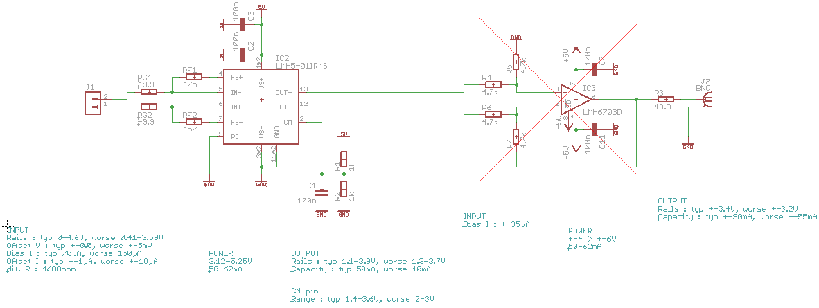
  • This is the actual schematic. The input signal is DC coupled, a -3dB cutoff at 500MHz will be the minimum acceptable, 1GHz will be fine.

    - The LMH5401 powering is driven by the input CM range of the dif signal (3-3.3V). Powering it in 0/5V force the output CM to be near 2.5V

    - The output may be positive of negative around 0V so the last amplifier must be powered symmetrically.

  • Hi,

    The OPA859 should work fine depending on what output range you are looking to drive. Will the VOL and VOH are ranging from -1.1V to 4.1V be fine for you?

    Thanks!
    -Karan
  • The OPA855 seems to be a best choice beceause of its Vin.max closer to Vs+ (0.6V below Vs+ for OPA855 and 1.6V below Vs+ for OPA859).

    But it is not fine enough.

    Even if I consider a 50mV signal at the input of the LMH5401 used as x4 preamplifier, the output of the preamp will be 2-2.25V because of the very limited range of the CM pin.

    No GHz op-amp powered in +-2.5V accepts this input range.

    A solution may be to use a 2-stages op-amp, the first one powered in -1/+4V and the second powered in -2.5/+2.5V, lowering step-by-step the mean voltage of my signal but it looks dirty.

    Any suggestion will be fine :)

  • Hello,

    I don't see any parts that would meet your specifications but what you are suggesting is a possible solution. You might just have to use multiple stages to complete what you need. You can try to do a TINA TI simulation before doing the design. Each part has a SPICE model in the tools & software folder. You can draw up the circuit with the parts you are using and quickly test it out.

    Thanks!
    -Karan
  • Hello Nicolas,

    I think what you are looking for is a standard gain of 1 diff to single stage. Running balanced supplies there, the grounded R on the V+ input is a reference for the output centering. So it will level shift the Vocm =2.5V from the LMH5401 to ground. Anyway, we did this exact job for the D2S input inside the THS3217 where I see close to 900Mhz SSBW as diff to single stage gain of 2 in the data sheet (to recover the backmatch in a doubly terminated line driver). Disable the OPS to use just the D2S.

    Or if you wanted to build yourself something like the attached using the THS4304 shows about 800Mhz SSBW. There is an adjustment to the equal resistors on the inverting side to balance input impedances. This is due to the V- input showing a dependent voltage swing. It is a simple calculation I have somewhere if you need more help there.I just guessed 200ohm for now. 

    Diff to single with THS4304.TSC

  • And, if you wanted to be a little more ambitious with the THS3217, you could run the D2S output through an equalizing (peaking) filter into the OPS stage and perhaps flatten this out further in frequency. Right now the plots are showing SSBW flatness through 500Mhz, but larger signal is going to run into Slew Limiting - although the SR on the THS3217 stages are far higher than the THS4304 to begin with.
  • Thanks for this advice, I will test 2 versions, one with the THS3217 and one with the OPA855 powered asymmetrically (-2.45/+2.8V) to meet both input and output voltage swing requirements.

    Nicolas