This thread has been locked.

If you have a related question, please click the "Ask a related question" button in the top right corner. The newly created question will be automatically linked to this question.

OPA551: Op Amp stability analysis request

Part Number: OPA551
Other Parts Discussed in Thread: OPA552

Hi guys

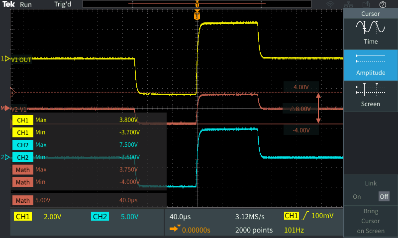
I'm using a Howland Current Pump to change the voltage to current. Just like this above picture,

when a resistive load is connected to the ground, a stable voltage/current is provided.

The voltage difference is exactly what I wanted.

Instead of connecting a resistor, I'm trying to connect a human wrist and have an institutional review board (IRB) approval.

When providing the same voltage input,

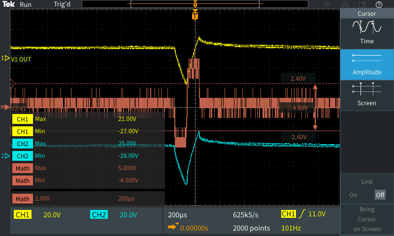
The voltage difference is similar, but I feel it is unstable.

I saw that when having a capacitive load, adding a resistor can make it stabilized.

However, I cannot determine what resistor value would be appropriate.

Can I get some advice to make this output to be stable?

  • Hi David,

    It is not clear from the DSO image if that is some sort of noise, or an oscillation on the middle trace. Oscillation is usually fairly uniform in frequency and often close to the unity-gain bandwidth frequency of the op amp. Since that trace is a math function (V2 - V1) and is noisy in appearance rather than a uniform oscillation, that tends to suggest that is the noise difference between V2 and V1. If you can capture a more revealing image of the V2-V1 trace that would be helpful.

    If you determine that it is indeed oscillation it would be necessary to have an understanding of what the load really consist of to perform a useful stability analysis. I expect a human body attached at the wrist to the Probe 1 circuit point is an impedance consisting of resistance and capacitance, but what the R and C values are is not obvious. It would be difficult to determine a compensation plan for the OPA551 circuit without the knowing the details of the load's electrical characteristics.

    Right now the circuit bandwidth is at maximum. You might want to increase Cf a bit and see if the noise/oscillation characteristic improves.

    Regards, Thomas

    Precision Amplifiers Applications Engineering

  • Hi David,

    I only want to remember that connecting electronic circuitry to a human body can be very dangerous! Are you familiar with the legal regulations you have to comply with when doing this?

    Kai
  • Thanks, Thomas. Sadly, I'm having a hard time understanding your words.

    Thomas Kuehl said:
    a math function (V2 - V1) and is noisy in appearance rather than a uniform oscillation

    The term "uniform oscillation",

    Thomas Kuehl said:
    Oscillation is usually fairly uniform in frequency and often close to the unity-gain bandwidth frequency of the op amp.

    can I ask the meaning of this?

    Also,

    Thomas Kuehl said:
    Right now the circuit bandwidth is at maximum.

    Can I ask the meaning of this as well, please?

  • Hi David,

    Thomas wanted to say, that your scope plot does not look like an oscillating OPAmp.

    If an OPAmp oscillates then it will do it at a frequency in the range of its unity gain bandwidth which is 3MHz in your case. Also, the oscillation will be constant and steady with a very high amplitude (from rail to rail) and a shape which looks like a distorted sine.

    Kai

  • Hi David,

    Do you understand Kai's explanations?

    Regards, Thomas

    Precision Amplifiers Applications Engineering

  • Sorry, guys.

    After reading some materials like this

    https://e2e.ti.com/blogs_/archives/b/thesignal/archive/2012/05/23/why-op-amps-oscillate-an-intuitive-look-at-two-frequent-causes

    I still didn't get it.

    kai klaas69 said:
    that your scope plot does not look like an oscillating OPAmp.

    Thanks for pointing that out.

    kai klaas69 said:
    unity gain bandwidth which is 3MHz in your case

    Bandwidth:
    – OPA551: 3 MHz
    – OPA552: 12 MHz

    Since I'm using a 100Hz signal, you are saying that my signal is in the bandwidth? (100 Hz < 3 MHz)

    kai klaas69 said:
    a shape which looks like a distorted sine.

    Well, each output from probe 1 and 2 showed a distorted sine wave, right? So I thought this was oscillating.

  • I apologize, Thomas. I think I lack some concpets of the Op Amp. I have to admit that I only know the basics (virtual ground, feedback loop).

    Although I read some articles about the instability of the Op Amp, I think I cannot catch up with your words.

    May I please ask for extra help?

  • Hi David,

    The center DSO image is the difference, or subtraction, of V2 - V1. It is a math function and not obtained from probing a different point in the circuit.

    If the V2 - V1 DSO trace appeared as a sine wave, then I would be confident to say that there is a stability problem with the circuit. However, the V2 - V1 DSO trace doesn't resemble a sine wave. It looks non-uniform from one point in time to the next; therefore, it looks more like noise. If you can enlarge the V2 - V1 trace so that it shows more details we might be able to determine if it is an oscillation, or not.

    If it is an oscillation, then the only way to compensate the amplifier is to have accurate information about the load the OPA551 current pump must drive. That may be difficult to obtain because the human body driven as you are attempting probably doesn't have an equivalent electrical circuit developed. The load needs to be thoroughly understood to perform a meaningful stability analysis and then develop a compensation plan.

    If you would like to know more about op amp stability I recommend studying the TI Precision Labs training videos. The videos cover many aspects of op amp electrical characteristics and behaviors. You can find a link to the op amp training here:

    training.ti.com/ti-precision-labs-op-amps

    I hope this helps.

    Regards, Thomas
    Precision Amplifiers Applications Engineering
  • Thomas Kuehl said:
    If the V2 - V1 DSO trace appeared as a sine wave

    You mean square pulse? (Since my input was a pulse train)

    Thomas Kuehl said:
    The videos cover many aspects of op amp electrical characteristics and behaviors. You can find a link to the op amp training here:

    I deeply appreciate your time. Can you spare me some time to follow up, please?

  • Hello David,

    You will note that the V2 - V1 noise-like waveform is present when the pulse is present, and when it is not present. If the OPA551 is oscillating the resulting V2 - V1 waveform would most likely be a sine wave, or a distorted sine wave. That is why we need more details about the waveform.

    Regards, Thomas

    Precision Amplifiers Applications Engineering

  • So actually Kai, I thinkthat is what David is getting ready to propose, that IRB reviews what you can do to human subjects,

    oprs.usc.edu/.../
  • Although it sure sounds like he already tried it on someone?

    David, that resistor to ground is not marked also where are you substituting a wrist - where the 1kohm between V1 and V2 are marked?