Hello team,
My customer is designing the current limit value of OPA547 with 56.33mA.
*Please see the attached file.
Please let me ask you two questions about the variation of
the current limit value.
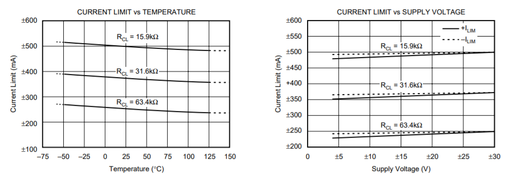
Q1) Could you please inform me of the variation of the current limit value
including the temperature influence?
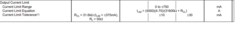
Q2) Could you please inform me of the variation of internal resistance,
the internal reference and the gain to estimate the variation of current limit
value when changing the external resistance value,if possible?
Sincerely,
Tsuyoshi Tokumoto