This thread has been locked.

If you have a related question, please click the "Ask a related question" button in the top right corner. The newly created question will be automatically linked to this question.

TLV3502: AC Drop Fast Detection Circuit in the TI Design "tidrv40a"

Part Number: TLV3502

Hi,

In this TI Design "tidrv40a",

http://www.ti.com/lit/df/tidrv40a/tidrv40a.pdf

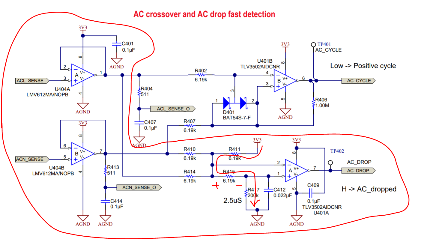
I don’t think this circuit will work normally as we want.

We can see from the capture above, while the AC input drops, that’s to say, the voltage at the left terminal of R410 and R414 would be 0.

In this condition, the voltage across R415 would continue to make the output of the comparator U401A low rather than turning into high level.


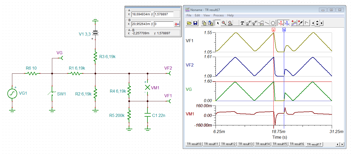
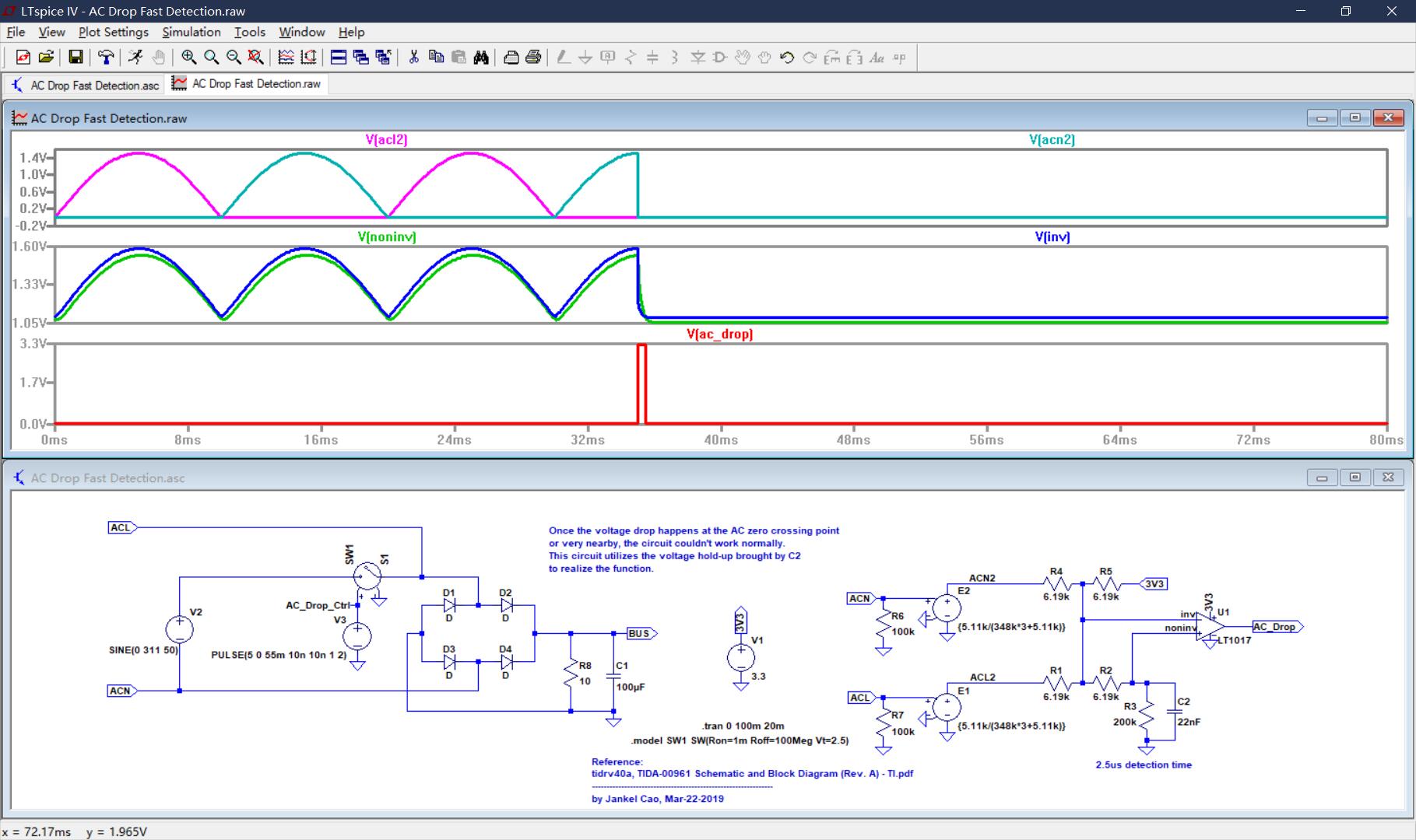
I also do the simulation of this circuit in LTspice and found it did work abnormally.

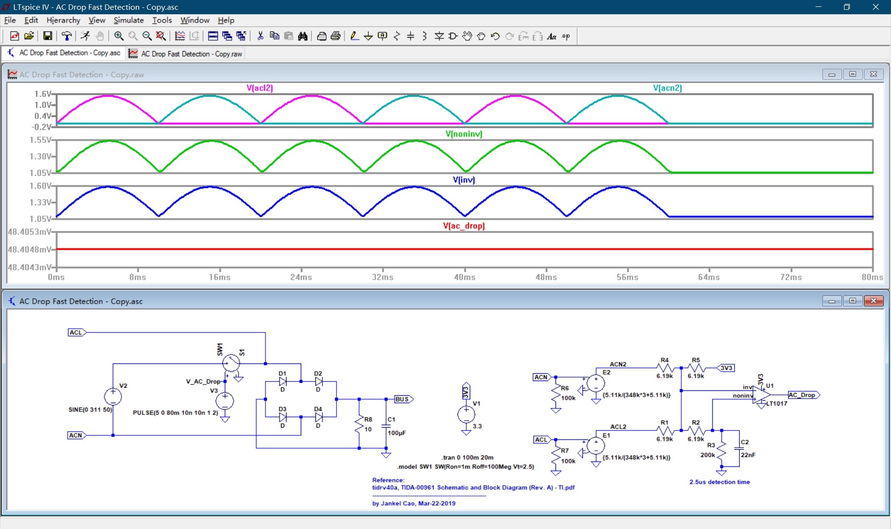
We can see V(ac_drop) is always low even when AC input drops.

If there would be someone could check it?

If it could work, please tell me how it works and why my simulation result shows it didn’t work normally??? Thanks a lot.


PS: The simulation file is attached.

AC Drop Fast Detection.rar

  • Jankel,

    Could you please attach a TINA (.tsc) or LTSPICE (.asc) file for me to review? I was unable to open your previously attached item.

    Regards,
    Jonny

  • Hi Jonny,

    I tried to download what I attached, and extracted it. I found it works. (The softwre I use is LTspice IV, you can use LTspice IV or XVII to open it.)

    Anyway, you could also try the link below.

    Link:

    PASSWORD: xpk6

    Validity: 7 days

    复制这段内容后打开百度网盘手机App,操作更方便哦

  • Hi Jankel,

    It seems that the inverting pin is always in phase and 50mV higher than the noninverting pin. This causes the output to always be low.

    The way the circuit is drawn up, I believe the inverting pin is summing divided down inputs from ACN and ACL, however R2 in your circuit is only dividing this signal down and not doing anything very meaningful.

    Thanks for bringing this up, I will have a discussion with our systems engineers to see how the part should correctly work.

    My question for you is what did you expect the trip point of the AC signal to be for the part to output HIGH?

    Regards,
    Jonny
  • Hi Jonathan,

    Hard to say. How can you figure out which input voltage point should I define as a trip point?

    Input voltage crosses 0.

    One of the way we could define this trip point is, I believe, integrating the input voltage and meanwhile dischaging, hence, another control signal is generated, we could use this generated signal to judge if the input voltage disappears. When no continuous input voltage exists, this signal will drop down.

  • Jankel,

    I'm still a little stuck on how exactly the circuit should function. I've forwarded this problem to a few different systems engineers and am awaiting their input.

    Just wanted to let you know I am still looking into this. I'll provide you any updates as they come along.

    Regards,
    Jonny
  • Hi Jonathan,

    Thank you for your effort.

    Looking forward to your reply.

  • From my understanding now,

    The circuit should be comparing the current AC input with the previous neutral line value (2.5us earlier) and senses if the ac signal is going low.

    In your simulation, it seems that your ACL and ACN become in phase at the node before it enters into the comparator input, causing the input to stay low. Unfortunately the systems team did not have access to the simulation file previously as the engineer who worked on the design left, but I will do my best to try and simulate the circuit to its intended function.

    Regards,
    Jonny
  • Hi Jankel,

    I think the circuit delivers what it promises:

    jankel1.TSC

    I have simplified the circuit a bit to make things clearer. The input signal is short-circuited at t = 18.75ms for about 2ms to simulate a fast (!) drop. As result VM1 changes its polarity for about 500µs, long enough to make the TLV3502's output toggle.

    Kai

  • Hi Jonathan,

    Thanks for your reply. You're right, it compares the current AC input with the the previous. (Combined with some other small tricks<R415>)

    Hi Kai,

    Thanks for your simulation result.

    Now I understand.

    I also get the worked simulation results as follows (I only change the voltage drop time instant in my previous simulation circuit, and then it worked.).

    BUT this circuit has a BUG/Defeat.

    This circuit utilizes the voltage hold-up brought by C2 to realize the function,

    SO, 

    ONCE the voltage drop happens at the AC zero crossing point or very nearby, the circuit couldn't work normally. (as my previous simulation result showed)

  • Hi Jankel,

    this is no signal off detection or anything else, but a fast drop detection. It detects whether there is a fast drop within (!) the regular puls train. To me the circuit does what it is supposed to do.

    Kai
  • Hi Kai,

    OK, thanks, I got it. This circuit only detects the fast drop of AC, but it doesn't detect the AC off.