This thread has been locked.

If you have a related question, please click the "Ask a related question" button in the top right corner. The newly created question will be automatically linked to this question.

OPA1632: 2nd order LPF using OPA1632, Single Ended to Differential

Part Number: OPA1632
Other Parts Discussed in Thread: THS4531A

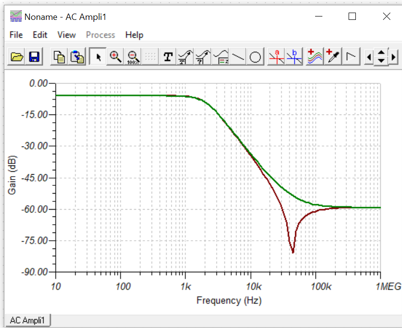
All the examples that I have seen when converting a single ended signal to differential have at most 1 low pass filter stage. Is it okay if I add a 2nd low pass filter stage? The circuit would be a 2nd order low pass filter, converting a single ended signal to differential. I modeled the circuit in TINA and the non-inverting output seems to be resonant at approximately 50KHz, but the inverting output seems fine.

  • Hi,

    Can you provide me with the TINA file that your built this circuit in. There isn't a problem in using a second low pass filter in your design. Upload the TINA file and I can test your solution. Is there a reason you want to use a second low pass filter?

    Thanks!
    -Karan
  • I believe that I did not have the FDA connected correctly in TINA - things make more sense now.

    I attached a screenshot of the output and am curious why the maximum attenuation is -60dB for the non-inverting output?

    OPA1632_2nd_order_LFP.TSC

  • Hello all,

    Your design is essentially a 2kHz gain of 1 Butterworth followed by a 722kHz RC pole once the feedback cap shorts out. The design is pretty high noise, I ran an integrated noise to 10kHz, 23uVrms.

    What is your minimum input resistor target, I can generate a lower noise solution pretty quickly with that if you would like.
  • Actually, just tried this - it appears that to keep the caps lower the R's are in fact pretty large, can't improve noise much.

    The R's dominate the output noise - not really using the great input noise of the OPA1632. If your application can use a single 5V solution, the THS4531A might be enough at much lower power.
  • Unfortunately, I have to use ±5V. The max input signal is ±3V, the min input signal is ±45uV. Main frequencies that I’m trying to filter out are at 3KHz, 5KHz, 12KHz, and 64MHz; hence why I want to keep the capacitor values and packages low to avoid capacitors with self-resonance frequency that are less than 64MHz. I have the power budget, so the resistors can be low – as low as what the datasheet recommends.
  • Understand, looks like you are using a 2.5V CM control? Now you know one of the magic things about FDA's is on a single supply they will take a bipolar input and level shift all the pins in range for a single supply if your intended output swing does not go below ground.

    The easy way to see this is if the output does not go below ground look at what the CM voltage swing will be on the lower divider path to ground - it always stays above ground, just like the signal side input so negative rail input FDA's on single 5V can work.

    I limit my MFB tool to max 33nF as the the current limit for low cost C0G caps. If you do that in a 2kHz design, your R's are going to be large.

    Anyway, I tried to describe FDA I/O range issues in this recent article - And then DC precision in a later one called Insight #4.

    www.planetanalog.com/author.asp
  • Good point, I'll look into the THS4531A. Thank you.