This thread has been locked.

If you have a related question, please click the "Ask a related question" button in the top right corner. The newly created question will be automatically linked to this question.

OPA209: OPA209 VOUT goes high in uncertain condition

Part Number: OPA209
Other Parts Discussed in Thread: OPA197

Hi Support team

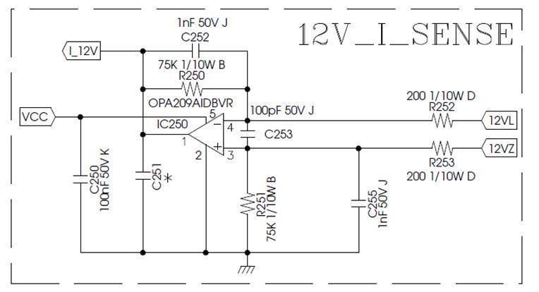
there is server PSU application, OPA209 was used in output current measurement, while turning off the 12V main output, only the standby output, in this condition, VCC is maintaining to 18V but there is no voltage on 12VL & 12VZ.

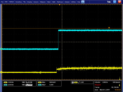
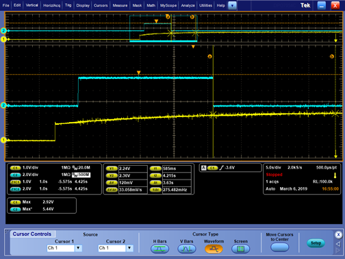
CH1 is the signal that IC250_Pin1 output is divided into MCU (UC_12V_ILocal), so the actual IC250_Pin 1 output will be larger than CH1.
CH2 is an Alert signal. When the MCU detects that the voltage of CH1 is greater than a certain level, it will pull low.

in case, we can observed that the abnormal waveform's CH1 single will goes high (around 2V) to trigger the alert signal but the normal one is 350mV only,

the failure rate is 8/900, and after process the FA, the return IC was passed the ATE

need your kindly help to check it and give some advice

thanks you

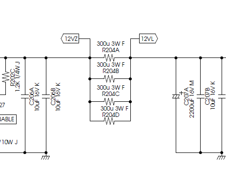
current shunt resistor

Circuit

normal waveform

CH1 is OPA209 PIN 1

abnormal waveform

  • Hi Red,

    the OPA209 cannot work with an input voltage which isn't at least 1.5V higher than GND. See the "input voltage range" specification in section 6.7 of datasheet.

    Kai
  • Hello Red,

    With the sense resistor current off 12VL and 12VZ will be pulled to 0 V by R251, and possible by something connected to I_12V point. That would constitute a input common-mode voltage (Vcm) violation as Kai identified. If the input of the OPA209 is biased outside of its specified linear Vcm range, and the output moves outside of its linear output operating region the op amp no longer function as a true operational amplifier. Once the input conditions are reapplied there will recovery times for the input and output circuits and just exactly how the op amp recovers is not specified. It is best not to run an op amp intended for linear operation in this manner.

    Can you reveal if C251 is installed and if so, what is its value? Also, can you provide the divider information connected to I_12V? I just want to make sure we have all the information.

    Regards, Thomas
    Precision Amplifiers Applications Engineering
  • Hi Thomas, 

    C251 is un-used.

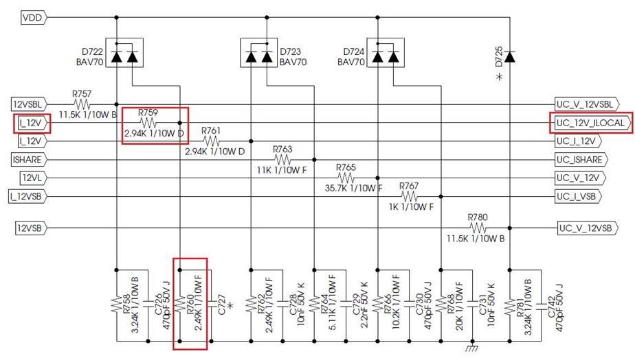
    I_12V divider information please refer below 

  • Hello Red,

    The output of the OPA209 will be pulled near 0 V by the output resistive divider when the input sense current is off. Since that is not necessarily a characterized, or tested condition it is not known how each individual op amp will behave.

    I suggest having the customer consider trying a high-voltage, Rail-to-Rail Input/output op amp such as the OPA197 in place of the OPA209. Not only is it specified with Rail-to-Rail Input/output, but on the first page of the OPA197 datasheet it lists under Applications using the op amp as a High Precision Comparator. Comparators operate with their output driven up against one swing limit or the other and their recovery characteristics are important for the application.

    The OPA197 is available in the same pinout DBV, 5-Pin SOT package as the OPA209. You can view the OPA197 datasheet here:

    Regards, Thomas
    Precision Amplifiers Applications Engineering