This thread has been locked.

If you have a related question, please click the "Ask a related question" button in the top right corner. The newly created question will be automatically linked to this question.

OpAmp selection for OPT101

Other Parts Discussed in Thread: OPT101, LMV641, OPA388, INA118, OPA189, INA819

WE ARE USING OPT101 PHOTO-DIODE ,IN OUR APPLICATION THE VOLTAGE OUTPUT AT OPT101 IS 1mV, WE WANT TO AMPLIFY THIS SIGNAL WITH VERY LOW NOISE. CAN ANYONE SUGGEST ME THE OPAMP SUITABLE FOR THIS? THE OPERATING REAUENCY IS 10KHz.

THE PROBLEM WE ARE FACING IS THAT OUR SIGNAL IS OF 1mV BUT THE NOISE OUTPUT AT THE OPT101 END IS AROUND 22mV. BECAUSE OF THIS WE ARE UNABLE TO DETECT THE SIGNAL. CAN ANYONE SUGGEST THE OPAMP FOR THE SAME AS WELL AS HOW TO REDUCE THE NOISE FROM THE SIGNAL.? 

  • Hi Jignesh,

    have you noticed that you can provide a low pass filtering with the help of a suited feedback capacitance?

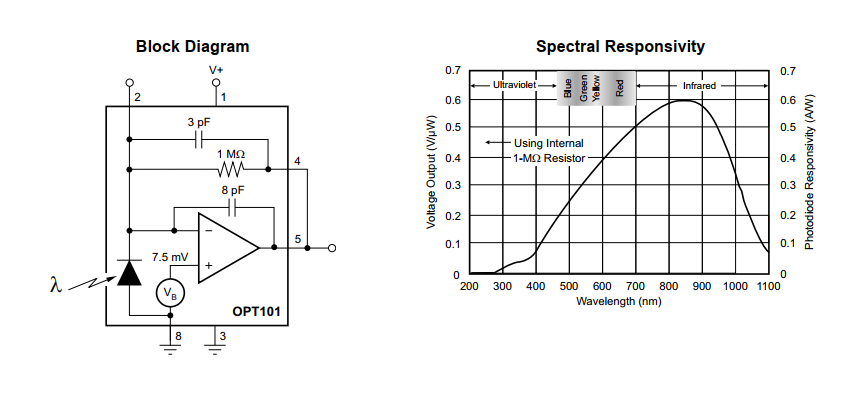
    How have you wired the OPT101? Can you show a schematic?

    Kai
  • Hello Jingesh,

    The OPT101 internal TIA uses a low noise op amp. The OPT101 datasheet graph in Figure 11, Output Noise Voltage vs Measurement Bandwidth, shows that the output noise is a function of the TIA resistor which sets the transimpedance gain and the bandwidth. For example, with a 1 Megohm feedback resistor and a 10 kHz bandwidth the noise will be about 200 uVRMS. That is considerably less than the 22 mV you are measuring. Therefore, it is likely that the light source the OPT is measuring has high noise, or external noise is being coupled into the OPT101 circuit. The key to obtaining much lower noise is to figure out where the noise is coming from that is corrupting the low noise performance of the OPT101.

    Kai mentioned adding feedback capacitance across the TIA gain set resistor. Certainly reducing the OPT101 bandwidth will reduce noise. However, doing so you may not have the bandwidth needed to recover the 10 kHz signal. Adding a low noise amplifier after the OPT101 output - even though its noise may be nice and low - will simply amplify the noisy signal coming from the OPT101.

    Regards, Thomas

    Precision Amplifiers Applications Engineering

  • YES. TRUE. BUT IN MY APPLICATION I HAVE TO RETAIN MY SIGNAL SHAPE AS MUCH AS POSSIBLE. AND AFTER REMOVAL OF NOISE CAN YOU SUGGEST ANY GOOD OP-AMP WHICH CAN AMPLIFY LOW VOLTAGE SIGNAL WITHOUT ANY ISSUE AND SHOULD HAVE HIGH GBP, BECAUSE THE USABLE FREQUENCY IS 10KHz. IF THERE ARE ANY , I WOULD APPRECIATE THE HELP. THANK YOU SO MUCH.
  • Hello Jingesh,

    What supply arrangement do you have available to power the op amp? What load must it drive?

    Regards, Thomas
    Precision Amplifiers Applications Engineering
  • I HAVE BATTERY OF 9V. THROUGH WHICH I AM OPERATING THE OPT101, I HAVE A REGULATED POWER SUPPLY IN LAB. THE OUTPUT OF THE OP-AMP WILL GO TO ADC FOR THE DATA ACQUISITION. WE NEED TO STORE THE OUTPUT OF SENSOR. BUT BEFORE THAT WE NEED A ADEQUATE AMPLIFICATION.
    THANK YOU SO MUCH.
  • Hi Jignesh,

    again, how have you wired the OPT101?

    And what is your signal shape?

    Kai
  • I HAVE WIRED THE OPT IN A PCB TRACK. AND THE SIGNAL SHAPE IS PULSE.
  • Hi Jignesh,

    so, have you connected pin 4 and pin 5 to each other? Or have you connected an external resistor as discussed in section 8.3.2.1 of datasheet?

    And what is the exact shape of your signal pulse? This is important because it impacts the filtering possibilities.

    Kai

  • Hello Jingesh,

    As far as recommending an op amp to follow the OPT101 stage here is a starting suggestion, LMV641. It will work nicely with your 9 V battery power because it operates with low current, about 160 uA. It has a 10 MHz gain-bandwidth, and 1 kHz voltage noise of 14 nV/rtHz. You can view the datasheet here:

    Regards, Thomas

    Precision Amplifiers Applications Engineering

  • THANK YOU SIR.

    THAT WAS GOOD SUGGESTION , ALTHOUGH I HAVE NARROWED DOWN LATELY TO OPA388,OPA189 AND INA118. CAN YOU TELL ME WHICH WOULD BE BETTER IN MY APPLICATION?

    THANK YOU SO MUCH. I APPRECIATE. THANKS.

  • Hello Jignesh,

    OPA388 - 2.7 V to 5.5 V supply, rail-to-rail input/output, ultra-low voltage offset/drift, 7 nV/rtHz 1 kHz en, 10 MHz GBW

    OPA189 - +/-2.25 to +/-18 V supply, but really optimized for higher supply voltage such as +/-15 V to +/-18 V, rail-to-rail output but not input, ultra-low offset/drift, 5.2 nV/rtHz 1 kHz en, 14 MHz GBW

    INA118 - Low-power instrumentation amplifier, Gain set by one external resistor, +/-1.35 to +/-18 V supply, but really optimized for higher supply voltage such as +/-15 V, not rail-to-rail input/output, low offset/drift, 10 nV/rtHz en ( G= 1 kV/V), 70 kHz bandwidth  G = 100 V/V.

    If you plan to use the a 5 V supply the OPA388 provides very high performance. If the supply voltage is higher such as +/-15 V the OPA189 would be the choice. An instrumentation amplifier such as the INA118 is easy to apply because it only requires one gain setting resistor. It provides certain advantages over a single op amp especially in differential input applications. Make sure the bandwidth meets what is needed for the particular gain you intend to set it to.

    They are all high performance amplifiers so which ever one you select the performance should be very good.

    Regards, Thomas

    Precision Amplifiers Applications Engineering 

  • Hello Jignesh,

    By the way, we have a brand new, higher performance replacement for the INA118. It is the INA819 and you will find several performance enhancements over the INA118. You can find the INA819 datasheet here:

    http://www.ti.com/lit/ds/symlink/ina819.pdf

    Regards, Thomas

    Precision Amplifiers Applications Engineering

  • THANK YOU VERY MUCH THOMAS FOR HELPING ME OUT. I REALLY APPRECIATE IT. THIS RESOLVE MY ISSUE.

    I HAVE USED INA118 AND I HAVE GOT THE AMPLIFIED SIGNAL. THANK YOU FOR  YOUR ADVISE. THANKS.