This thread has been locked.

If you have a related question, please click the "Ask a related question" button in the top right corner. The newly created question will be automatically linked to this question.

TIA

Other Parts Discussed in Thread: OPA197

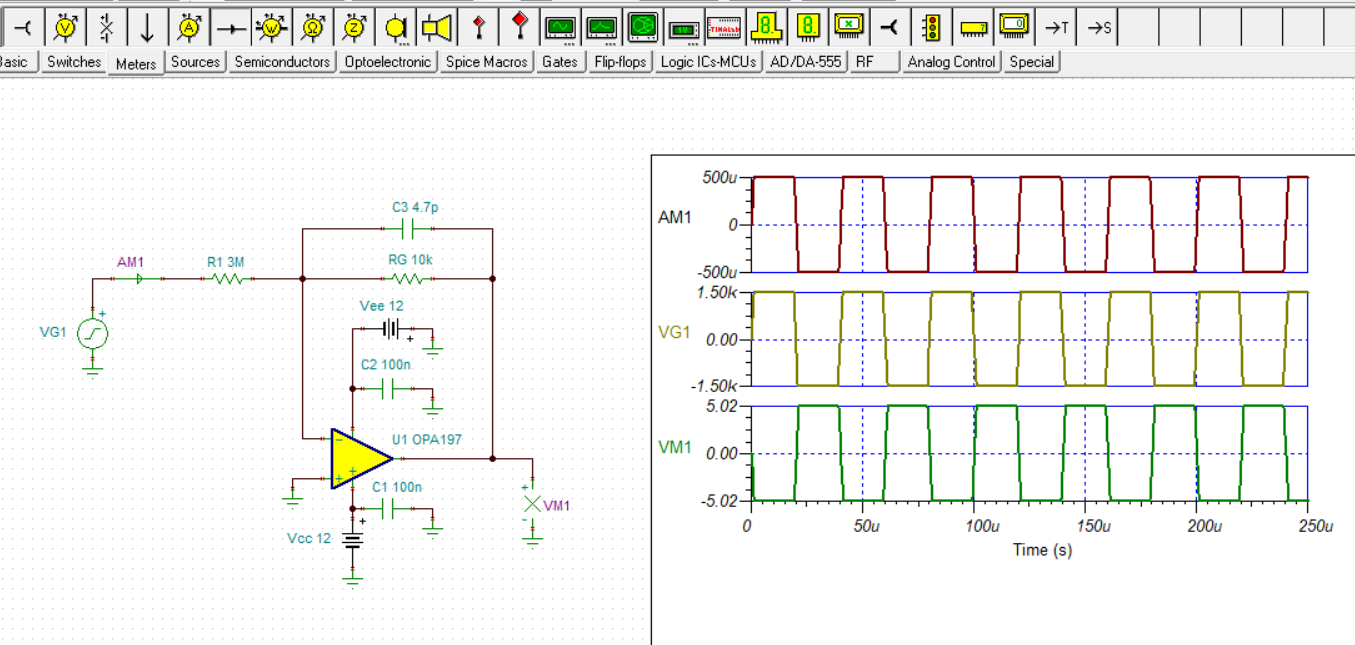
Hello everyone, can I convert the weak current signal into a voltage signal and amplify this signal? Which chip should I use?

  • Hi
    If you want to transfer tiny current(uA) into voltage signal. TIA could be a good structure.
    To determine the right Op Amp, you need to define your system design.
    To start, I suggest you figure your input signal, amplitude, frequency and output signal, amplitude.

    Thanks!
  • Hi,

    yes, a TIA can be used for this. What is your signal current? Where does it come from?

    The OPAmp should have an input bias current which is negligible compared to the signal current.

    Kai
  • Hello user5994204,

    A TIA is the most common and direct way to convert input current to output voltage. If you can provide answers to the following items it will help us zero in on the most appropriate op amps for the application:

    1. Input current range
    2. Output voltage range
    3. Bandwidth requirments
    4. Supply voltage(s)
    5. Output load
    6. Package type
    7. Any other important performance requirements; noise, temperature, etc.

    Regards, Thomas

    Precision Amplifiers Applications Engineering

  •        Thank you for your reply !   For the points you rasied, there are the following

    answers.

    1. Input current range :    0.3uA ~0.5mA
    2. Output voltage range  :  -5~+5v
    3. Bandwidth requirments :The square wave signal frequency is 10KHz-20KHz
    4. Supply voltage(s): ±5V  or ±12V  (Or any voltage between them)
    5. Output load : The output signal enters the acquisition board
    6. Package type :No requirement about this
    7. noise :I have no idea about it.Because this process is : a bipolar square wave signal pass through a very big resistance (about 3MΩ), then the output weak current is converted into a voltage and amplified by the TIA, and then the voltage signal enters the acquisition board. It doesn't related to  the sound signal in this process, so I don't know how to determine the noise indicator.
    8. temperature,:No requirement about this..        

              The best wishes for you.

  • Thank you for your reply !

    signal current from 0.3uA to 0.5mA
    and the process is : a bipolar square wave signal pass through a very big resistance (about 3MΩ), then pass through TIA, and then the voltage signal enters the acquisition board.
    The best wishes for you.
  • Thanks for your reply.

    this process is : a bipolar square wave signal (±5V -±12V ; frequency 10KHz-20KHz)pass through a very big resistance (about 3MΩ), then the output tiny current is converted into a voltage and amplified by the TIA (the output voltage is ±5V), and then the voltage signal(±5V) enters the acquisition board.

                                                            Thank you !

  • Hello user5994204,

    You indicate that the 25 kHz input square wave is converted to a +/-500 uA maximum current via the 3 Megohm input resistor to the TIA. Based on your inputs I have put together a preliminary TIA where for a +/-500 uA square wave input signal produces a +/-5 V output voltage. A 10 kilohm gain set resistor is used to establish a transimpedance gain of 10 kV/A. The TIA output voltage is on the order of +/-3 mV, with the +/-0.3 uA minimum input current.

    Do realize that the input voltage driving the 3 Megohm resistor would have to be +/-1.5 kV for that level of output current. If that is the case make sure the 3 Megohm resistor is designed to handle that high voltage and does not breakdown, or have an external leakage path around it. If that high voltage were to reach the TIA op amp input that would pretty much assure its destruction.

    I selected the OPA197 for the TIA op amp. It has low input bias current, low noise, wide bandwidth and everything your TIA needs for high performance. You can find the OPA197 datasheet here:

    http://www.ti.com/lit/ds/symlink/opa197.pdf

    I put together a preliminary TINA circuit and modeled the transient response. More development may be needed, but consider this a starting place. Most any op amp driving the input of an ADC will require an RC network between the op amp output and the ADC input.

    Here's the TINA file:

    OPA197_I_to_V_01.TSC

    Note that your application first does a voltage-to-current conversion, followed by a current-to-voltage conversion. If you want you may be able to simply set up a voltage divider with the 3 Megohm resistor and a 10.033 kilohm resistor to ground. Then buffer the divider output with an op amp buffer stage. That would result in a non-inverting amplifier solution having wider bandwidth. You may want to try simulating that idea and see if it does what you need.

    Regards, Thomas

    Precision Amplifiers Applications Engineering