Because of the holidays, TI E2E™ design support forum responses will be delayed from Dec. 25 through Jan. 2. Thank you for your patience.

This thread has been locked.

If you have a related question, please click the "Ask a related question" button in the top right corner. The newly created question will be automatically linked to this question.

TINA/Spice/THS4521-HT: Input Common Mode problem or Tina Spice model error

Part Number: THS4521-HT
Other Parts Discussed in Thread: TINA-TI, ADS1278, , THS4521, THS4551, TL072, THS4521EVM

Tool/software: TINA-TI or Spice Models

Hi There

I have a low frequency (say 10Hz) differential input signal coming from a sensor centred around 1.65V and swinging down to 0.3V and up to 3V

The intent is to buffer this with a unity gain differential buffer and feed into a ADS1278 ADC. I'm hoping to use the THS4521-HT to do this (its a high temp application), my supply rails will be 0V and 3.3V

In terms of the output voltage swing of the THS4521-HT it can go down to 0.09V and upto 3.11V (typ at 125 degrees), this should be fine for my application.

In terms of input common mode limits, i'm unsure if its my calculations / understanding or the Tina Spice model for the THS4521.

Having read tech note "Analysis of fully differential amplifiers" and watched the training video "

16.2 TI Precision Labs – Op Amps: Fully Differential Amplifiers – Input and Output, Common-Mode and Differential-Swing Analysis"

using both these methods (see pic below) i get a input common mode of 1.65V. (gain of 1, sensor common mode and the output common mode 1.65V.

So my understanding there is no AC (peak to peak) component to worry about for the input common mode voltage for a fully differential input and output configuration?

so therefor 1.65V is within the limits of the THS4521-HT specs (0-1.8V for a 3.3V supply)

However when i simulate the following circuit it works with the model i got from another post and edited (https://e2e.ti.com/support/amplifiers/f/14/p/530720/1931878?tisearch=e2e-sitesearch&keymatch=THS4521%20common%20mode#1931878

Tina file here (with the working op amp - replace with website model to see distortion)

0218.THS4521_72216.TSC

Basically i want to know if

1) is there a problem with my understanding or is there a problem with the tina model on the website?

2) if its my understanding any suggestions of how to interface the signal at the top to the ADC1278?

Kind Regards

Martin

16.2 TI Precision Labs – Op Amps: Fully Differential Amplifiers – Input and Output, Common-Mode and Differential-Swing Analysis

  • If it helps, here a few plots to show you what i mean

    top pic is the model i got from a post on this forum, bottom pic is using the website model

  • As I understood your question you have a single ended input to diff. out. That is different in input swing than diff in to out. I discussed the I/O swings for different configurations in detail for the FDA in the THS4551 data sheet, and then kind of summarized in this recent article - for single to diff. the inputs have a common mode swing around a mid point that is easiest to see looking at the swing from the non-signal input at the output pins side back to the other input as a simple voltage divider.

    www.planetanalog.com/author.asp
  • Hi There

    many thanks for getting back to me

    I've looked at the post but my application is differential to differential

    my sensor is outputting a differential signal centred around 1.65V, I was planning on setting my THS4521-HT output common mode to 1.65V. Therefor the input common mode is also 1.65V (or at least I thin it is), if not what should it be?

    However I have used a Tina model found on this forum (attached in my post), this seems to work. If I swap the 4521 model for the one downloaded from the website or taken from the library the circuit stops working. So i'm to understand if my understanding is wrong or the website tina model is wrong?

    Kind Regards

    Martin

  • HI Martin,

    Could you please send me the thread ID from which you got the working model so I can investigate why there are two models showing different results?

    Thanks
    Christian
  • Hi Christian

    i'm not sure where you find the ID number for the thread but here's the link and title

    Title: Can THS4521 accept negative inputs when powered by single supply?

    Link:

    here's a screenshot of where I got the model from - towards the bottom of the thread

    Kind Regards

    Martin

  • Hi Martin.

    looks like your input signal is too high. When decreasing the signal amplitude from 1.0Vp to 0.8Vp the distortion dissapears.

    The model from the link (without distortion) is from 2009 and the model from the actual TINA-TI reference design (with the distortion) is from 2016.

    Kai
  • Hello guys,

    So the setup looks fine to me, the 2009 THS4521 model runs fine in terms of clipping - it had a lot of other problems in terms of noise and Aol that were updated in the 2016 model that shows clipping.

    The THS4551 was the major upgrade to the THS4521 in terms of physically better noise offset and modeling. If I drop it into the sim, it shows fine I/O swing shapes - I would have to suspect the THS4521 model Dec. 2016 upgrade messed up the I/O ranges at this point. You probably should be using the THS4551 anyway, and its model. Your test circuit with THS4551 attached.

    1kHz THS4551 model.TSC

  • And I do see you are using the HT version - at the die level, if the THS4521 works at high temp, so will the THS4551 - perhaps an HT package version for the THS4551 should be on the roadmap - we were basically moving all the designs we could from the much higher noise THS4521 to the improved THS4551 upgrade.
  • Hi Martin,

    this thread is a good example, why one should not trust the simulation too much. Do never expect seeing the whole truth when running a simulation. The main part of the developing (>90%) is always the measurement, even today...

    Kai
  • Good point Kai,

    but most designers and apps folks have to try and trust the models as a first step - the real point is how uneven outgoing quality control is on the models - and that applies industrywide. I test models all the time, and it amazing what you find what is missing. One of the more recent flareups of uncertainty was if there is, or should be, a consistent polarity on the CMRR error in the model (and of course the part itself) I have found TI models (and a recently updated ON op amp model) that switched polarities from the original model to recent updates? There was even a precision labs claiming CMRR in a uV/V sense was quassian centered on 0. I find that hard to believe - the mean value in dB is infinite - no, I think each input stage topology has a centered distribution in one polarity with some spread around that that does not cross zero - but not sure at this point.
  • That CMRR model polarity test shows up in this article - coming from CFA background, CMRR always contracts the gain in a uV/V sense - full transistor level VFA models seem to also, but macromodels seem random and changing - not a big effect, but interesting.

    www.planetanalog.com/author.asp
  • Hi Michael,

    I cannot count how many times I have got a bloody nose from simulations that gave improper results from whatsoever reasons...

    I find the simulation very useful when it comes to phase stability analysis of low frequency OPAmps like TL072 and such. It helps a lot to find the correct value of phase lead capacitance when some capacitive load is expected to be connected to the output of OPAmp. Then, even with an estimated open loop output impedance (to allow for much safety headroom...) the simulation usually gives qite useful results. Some decades ago when SPICE wasn't available or affordable I wrote simulations in QBASIC to be able to perform a simplified phase stability analysis. I even did it with the "Sinclair ZX Spectrum". Haha...

    Of course, I notice very well that the models are becoming better and better today. But I still don't trust the simualtions when it comes to the "fine structure" of performance.

    Wouldn't it be the perfect job for you as an absolute expert in these things to fix all the TI's models? Ok, let's say at least the major mistakes, for the beginning? :-)

    Kai
  • Fixing the AC errors in the THS4521 was in fact one of my efforts - what has changed in an uneven way is to get more AC accurate open loop output impedance models - generally, the RR output stages are quite messy physically - but very uneven as to which older models have that correctly done. And again, this is not unique to TI - testing a lot of ADI models over the years and they are not wonderful on this output impedance issue.

    At the device design review level, we see not only nominal performance issues but process and temp spreads - the latter never get into the customer models.
  • Hi Michael,

    of course, inaccurate models or better say incomplete models is not a TI issue. Not at all. This is really widespread throughout all chip manufcaturers. Just the opposite, TI is doing quite a lot to improve the models. I really appreciate it.

    I wished the models could properly simulate input voltages exceeding the common mode input voltage range as this can so often be seen in industrial applications, especially when powering-up or -down OPAmp circuits. So far the only remedy is to clamp the input voltages to the supply rails and use resistive voltage dividers behind to guarantee that the input voltages never exceed the common mode input voltage range. But this can become tricky from time to time, especially in HF circuits.

    Kai
  • FYI

    just to wrap this up

    1. I think from the testing I did and the comments here the conclusion is there is no common mode problem with the THS4521, its a problem with the 2016 Rev D Tina model
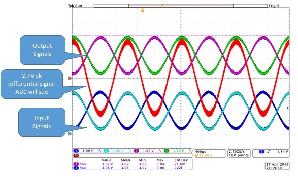
    2. I purchased the THS4521EVM and conducted a few tests and the results are as per the datasheet (clipped when I expected it to, input common mode is quite good (remember the common mode on the actuals input pins can be different to the common mode of the signal source)
    3. The equations in the following training video are a good starting point for people trying to understand fully differential amps (calculating input common mode in a fully differential amplifiers is different to normal op amps)

    https://training.ti.com/ti-precision-labs-op-amps-fully-differential-amplifiers-input-and-output-common-mode-and?cu=14685

    4. for completeness here a scree shot of my EVM waveforms

    thanks for all the comments

    kind regards

    Martin

  • Hi Martin,

    that's good news!

    Kai