This thread has been locked.

If you have a related question, please click the "Ask a related question" button in the top right corner. The newly created question will be automatically linked to this question.

INA213-Q1: TRANSIENT - PULSES in the Input supply of the Amplifier_Is it damage the Opamp

Part Number: INA213-Q1
Other Parts Discussed in Thread: INA213, INA190, INA186

Hi Team,

We are going to use INA213-Q or INA213AQDCKRQ1 part in our design.

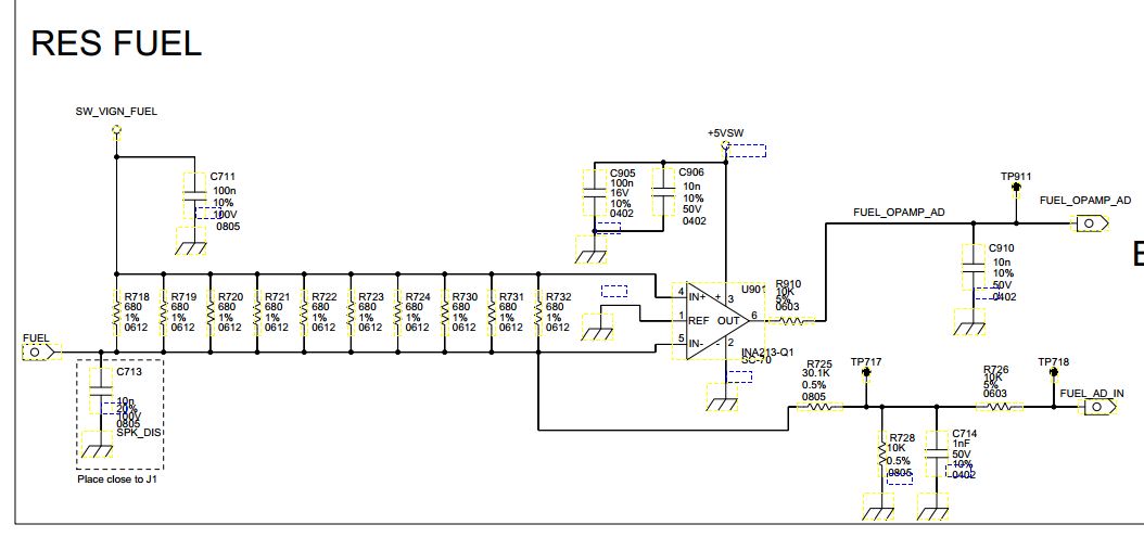
We have transient pulses test case at SW_VIGN_FUEL supply. Is it affect your operational amplifier.

Refer the transient specification table below : 

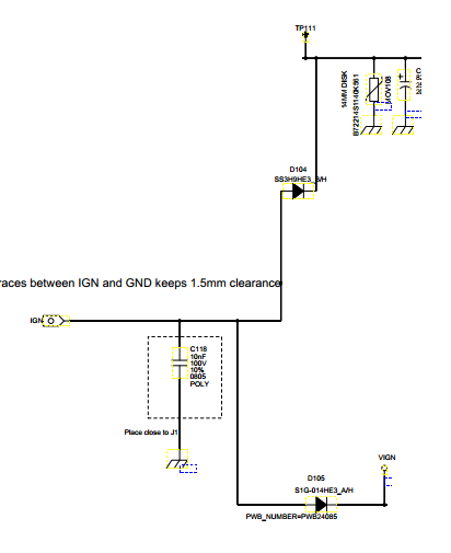
We have voltage limitation circuit before of that SW_VIGN_FUEL. It is generated from VIGN.

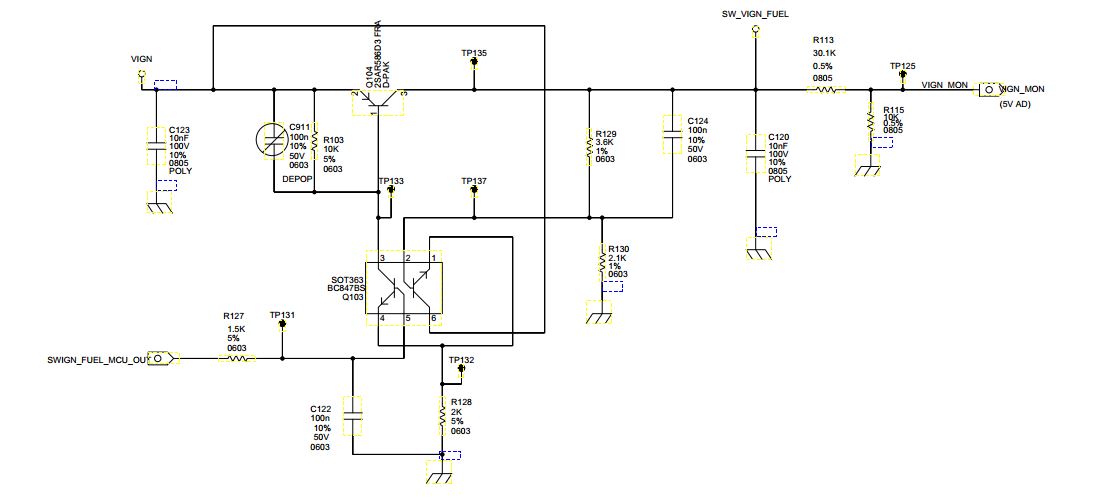
We have diode and MOV in the path.

  • Hey Selva,

    Thanks for posting on the forum.

    • Is the voltage transient location occurring at VIGN or at SW_VIGN_FUEL?

    • Would you help me understand what the voltage will be at IN+/IN- pins of INA213 when the transient pulse is at its peak?

    If the common-mode voltage (VCM) at IN+ and IN- pins is >26V or <-0.3V and this occurs for more than hundreds of nanoseconds, then you need to clamp the voltage at input pins (IN+/IN-). This technique is shown in Figures 27 and 28 of datasheet:

    If you need to protect against negative VCM voltages for VCM<-0.3V, then you will need additional TVS diodes clamped to supply voltage. Consider reading these FAQ posts for more information:

    If at some point you need to increase the current-limiting resistor (Rprotect in the datasheet Figures 27 and 28) from 10-Ohms, but don't want to decrease accuracy, then please consider using the INA190 or INA186. These devices have higher input impedance and thus can handle higher Rprotect resistor values (up to 1kOhm). Increasing Rprotect allows for use of lower power clamping diodes.

    Please post back with your questions.

    Sincerely,

    Peter Iliya

  • Hi Peter,

     Thanks for the immediate response.

    1. The transient Pulses feed at VIGN supply. SW_VIGN_FUEL supply is generated from the VIGN supply only. (Using transistors voltage limit circuit was designed.)

    2. As per the transient pulses ~40V will be comes in the +Ve and -Ve pin of the amplifier at positive transients.

    3. At negative transient pulses ~ 200V will be comes  in the +Ve and -Ve pin of the amplifier.

    4. Can you please suggest the TVS with low leakage part to withstand around +/-300V.


  • Hey Selva,

    I am not sure what you mean with "+Ve" and "-Ve" pins. I assume you mean IN+ and IN- pins of the INA213 device.

    If this is the case and +40V and -200V pulses are reaching the +IN and -IN input pins of the INA213, then clamping protection diodes are required as seen in my previous post.

    Here is a TI Reference design showing data on protecting the INA21x with TVS diodes. In this design 600W TVS diodes are used and should easily clamp +-300V pulses.
    www.ti.com/.../tidu473.pdf

    You can search for other TVS diodes here:
    www.digikey.com/.../144

    It is difficult to know what diode would work best for your system without knowing the following:
    1. What is maximum voltage the INA213 still needs to sense current at?
    2. How long do the voltage transients last?
    3. What is the maximum error your current sensing circuit can have?

    Sincerely,
    Peter Iliya