This thread has been locked.

If you have a related question, please click the "Ask a related question" button in the top right corner. The newly created question will be automatically linked to this question.

LM324: How to design filter to filter 450Hz/25KHz@-40dB?

Part Number: LM324

Hi Sir

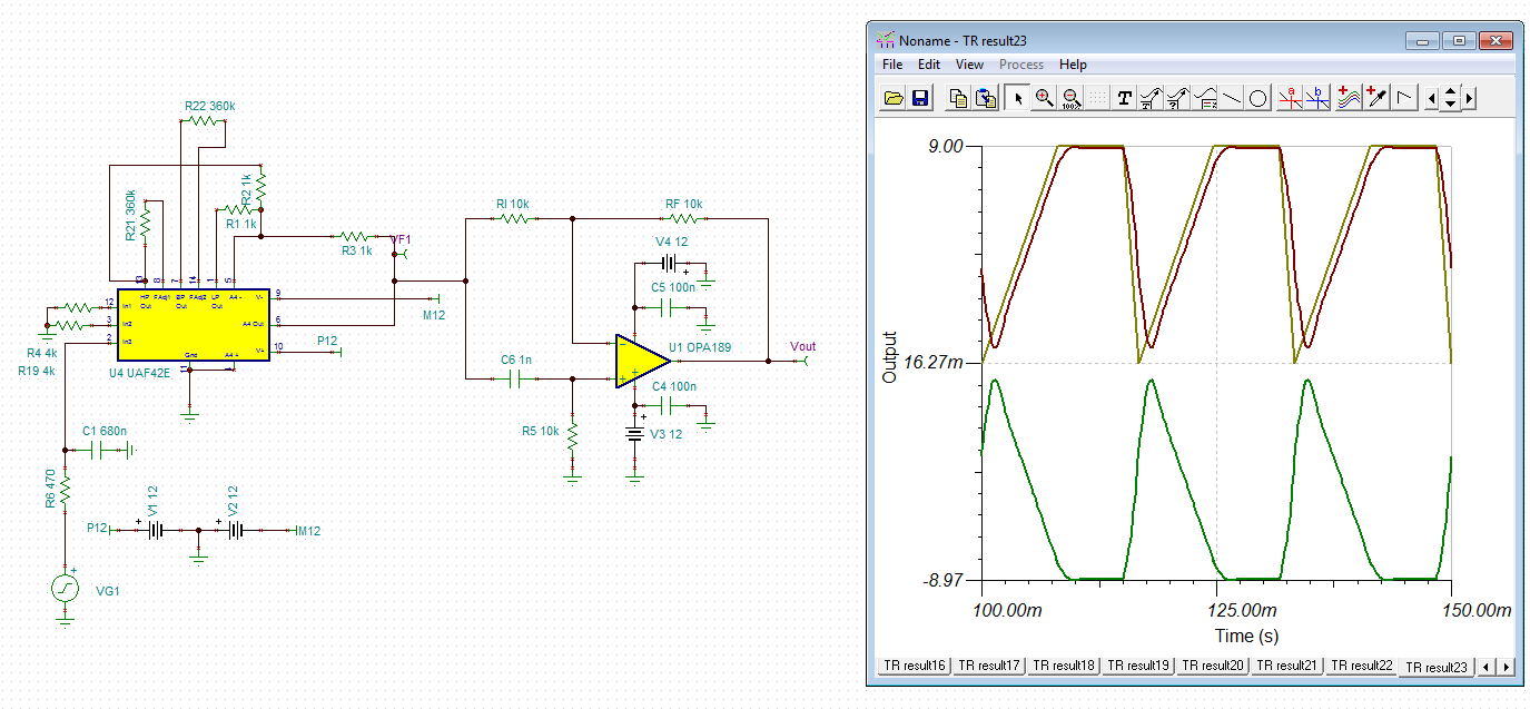
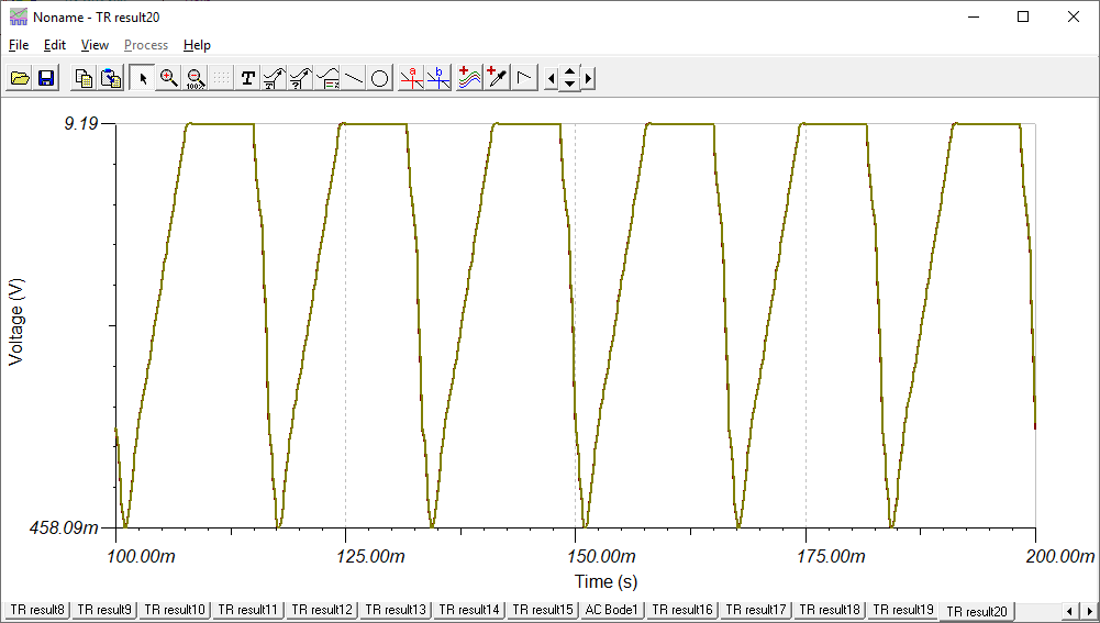
Our signal as attached file, Vcc = 5V,We want to filter 450Hz/25KHz@-40dB, and our center freq=60Hz.

May you have suggestion how to designfilter.docx?

                                                                                         Bogey

  • Chen,

    The document has time based signal waveform in it. Alos the center frequency mentioned (60Hz) is outside the lower and upper bounds ( 450Hz , 25,000Hz)

    What is the desired gain in the passband and how wide is the pass band?
    What is the desired attenuation in db/decade for low and high band block? [20, 40, 60 dB/decade]
  • Hi Ronald,

    Here are my answers:

    What is the desired gain in the passband and how wide is the pass band?

    [] gain=0 dB, center frequency=60Hz, BW=20Hz.

    What is the desired attenuation in db/decade for low and high band block? [20, 40, 60 dB/decade]

    [] 40dB

    System control signal is 60Hz as attached file, but the system has noise @ 450Hz and 25KHz.

    It is expected that the out-band noise 450Hz and 25KHz can be solved by filter.

    But the filter we designed causes the control signal to have distortion, how to design filter for this?

  • Tseng,

    I understand better now. I will simulate a filter on Monday. 

    Is the distortion you have now servere (visible on oscilloscope  waveform) or slightly higher THD+N?

    If LM324 output has to change between sourcing and sinking output drivers, then there may a be a ~4us delay in the output waveform. Try adding a 1k resistor from output to GND or to 5V as a test.

    This should be read by anyone using this device in a new application. Even those who use this part all the time will learn something new.

  • i sir,

    I use TINA and webench's simulation tool to find the right component. 25KHz noise can be solved with LPF and is easy to design. But I have not yet found a suitable 450Hz solution to meet the requirements of MEMS control system. I tried LBP, BPF and notch to reduce the 450Hz harmonic, the best simulation result is UFA42 notch filter, the results are as follows. But we can find some distortion in the waveform(vout/VF1).  

    If possible, please suggest a suitable  schematic. Thank you.

    450_notch.TSC

  • Hi Tseng,

    this comes form the abrupt changes and sharp edges of your input signal. A bit input low pass filtering can help. Also, your input signal amplitude is too high and drives the output into saturation.

    tseng3.TSC

    Kai

  • Tseng,

    I compared Vout with the input signal VF1 with a gain of -1. See how it overlaps. That means the notch filter didn't distort the signal.

    It was distorted before it reached the filter.

    450_notch+inv.TSC

  • Tseng,

    OK, I now see that you already knew VF1 was distorted. I'm not familiar with the AUF42E but I believe it is overdriven.
  • Tseng,

    I built another simulated circuit. 450 Hz notch also reduces the 7th and 8th harmonic of your complex signal period. The distortion happens because the notch filter removes this harmonic. 

    Here is the alternative circuit I tested. Fliege + LPF.TSC