This thread has been locked.

If you have a related question, please click the "Ask a related question" button in the top right corner. The newly created question will be automatically linked to this question.

OPA4727: Phase Reversal?

Part Number: OPA4727
Other Parts Discussed in Thread: OPA4191

I'm seeing what looks like phase reversal in OPA4727. Has this been seen before. VCC is around 9V.

I like the voltage specs of the op amp and the trim, but I don't need the speed. It seems to latch in my circuit.

I don't wish to post the circuit - can someone email me?

Thanks,

Paul

  • Hi Paul,

    have you noticed figure 29 of datasheet of OPA4727 and the according text?

    Kai
  • Thanks Kai,

    I have a better description of the problem now. The op amp latches on startup, in an unrecoverable fashion.

    Curiously it can latch either high or low. I tried adding diodes between inputs in rails but didn't improve anything,

    which makes sense according to the datasheet which I didn't see.

    Only some devices seem to have a problem in the circuit but enough do to be a problem.

    Do have a minimum value for a resistor that would solve the problem?

    But better, do you have a recommendation for a replacement op amp?
    Vsupply > 9 volts
    Input offset < 40 uV
    Slower is better than faster
    Good drift over temp specs
    ~$2.50 or less in qt 100 or so

    Thanks much,

    Paul

  • Hi Paul,

    having clamping diodes from the input to the supply rails is a good idea. The BAV99 is well suited. You could even think about using Schottky diodes, like the BAT54. But you should additionally insert a current limiting resistor between the clamping diodes and the input of OPA4727. Figure 29 of datasheet and the absolute maximum ratings say that the current must be limited to 10mA. But it's wise to limit the current even further. I would set the current limit to 1mA. You know how to calulate the current limiting resistor from this?

    Kai
  • You know how to calculate the current limiting resistor from this?

    Yes I do - sorry - it was right in the app note.

    Paul
  • Hi Paul,

    what clamping diodes do you use? And have you limited the current through the clamping diodes as well?

    Kai

  • Hi Paul,

    Take a look at the OPA4191. The 1k cost is a bit higher than the price you list. Cost is something you could discuss with your TI sales rep.

    www.ti.com/.../OPA4191

    This is a very modern, high precision op amp featuring:

    Low Offset Voltage: ±5 µV
    Low Offset Voltage Drift: ±0.1 µV/°C
    Low Noise: 15 nV/√Hz at 1 kHz
    High Common-Mode Rejection: 140 dB
    Low Bias Current: ±5 pA
    Rail-to-Rail Input and Output
    Wide Bandwidth: 2.5-MHz GBW
    High Slew Rate: 5 V/µs
    Low Quiescent Current: 140 µA per Amplifier
    Wide Supply: ±2.25 V to ±18 V, 4.5 V to 36 V

    Regards, Thomas
    Precision Amplifiers Applications Engineering
  • Hi Paul,

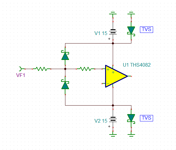
    I would do it this way (picture is from another thread):

    The left resistor limits the current through the clamping diodes and the right resistor limits the residual current into the OPAmp. This scheme has the advantage that the source resistance seen by the OPAmp input can be kept low without allowing too high input currents. I always use this scheme at the input of a circuit when the signal comes from outside.

    Kai