Other Parts Discussed in Thread: TINA-TI,
Tool/software: TINA-TI or Spice Models
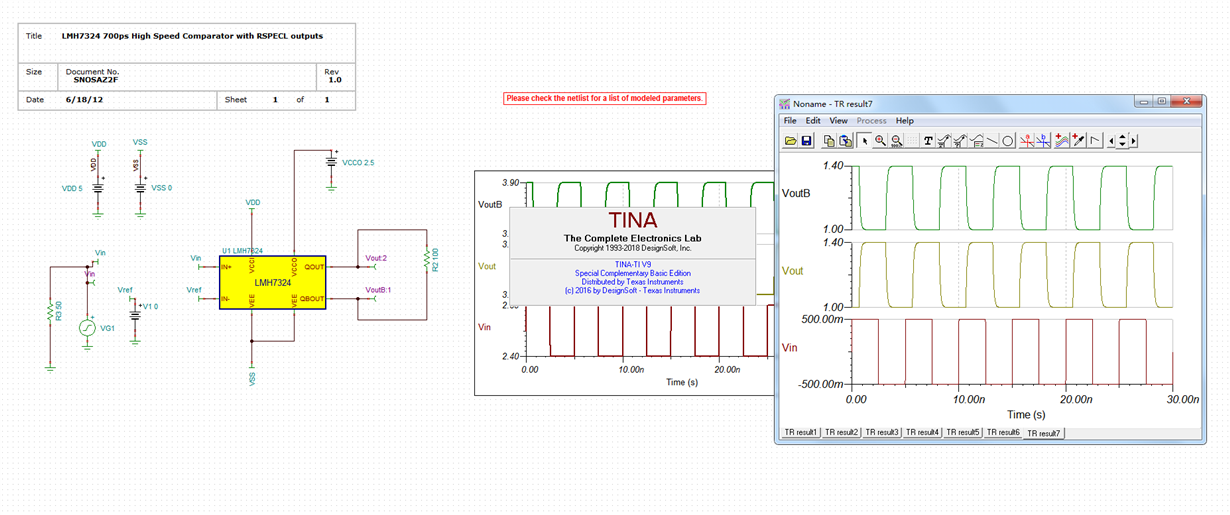
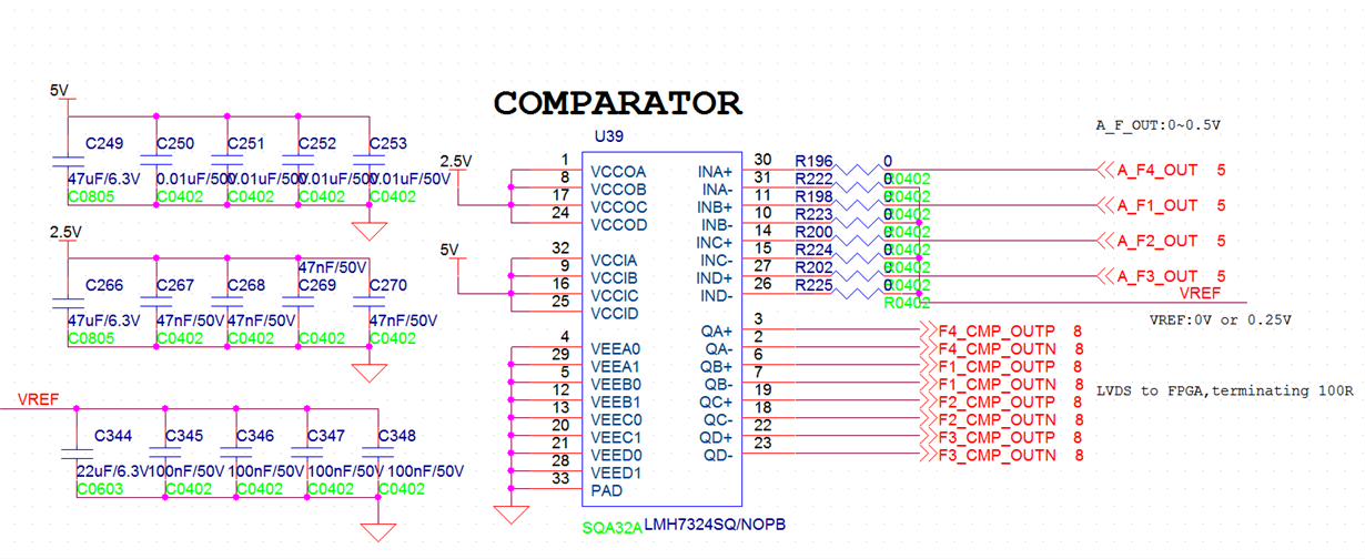
We are based on the following simulation graphic design,The output is an LVDS to xilinx's FPGA。The board we designed is tested with a standard square wave signal output by a signal generator and designed as a zero-crossing comparator,but the outp and outn all is DC1.8V, What is the reason for this?,must use VT (VT=VCCO-2V=0.5V)Provide offset current?


