This thread has been locked.

If you have a related question, please click the "Ask a related question" button in the top right corner. The newly created question will be automatically linked to this question.

AMC1300: 10mVpp differential "noise" on output

Part Number: AMC1300
Other Parts Discussed in Thread: TLV712

Hi Guys

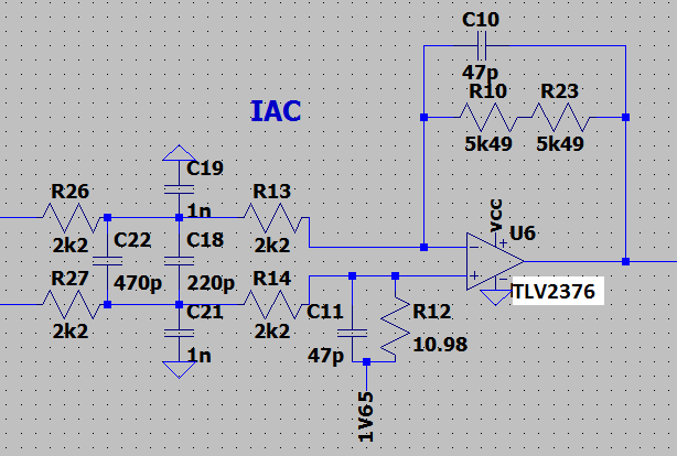
I'm trying to use the AMC1300B to measure a 1mR shunt resistor. For the most part it's working well (good accuracy) but I am getting more noise than I expected on the output OUTP OUTN. For my tests I have isolated the circuit down to the shunt resistor (0A) and OUTP-OUTN terminated into 3k3 at the legs. I am supplying both rails at 5V with separate bench supplies.

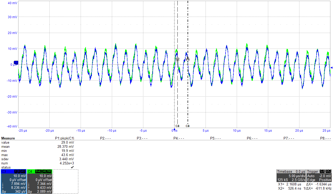
Common mode (OUTP or OUTN to GND2) they exhibit a 20mVpp oscillation at about 600kHz (should I suppose this is the SD modulation frequency?) and in the real circuit this is rejected by the differential amplifier:

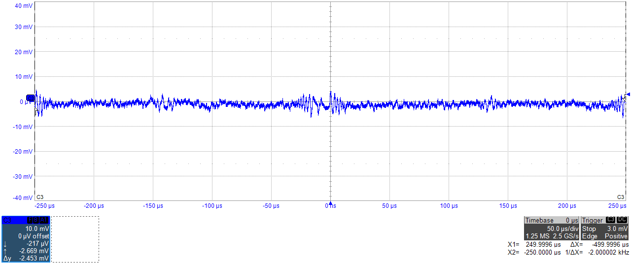
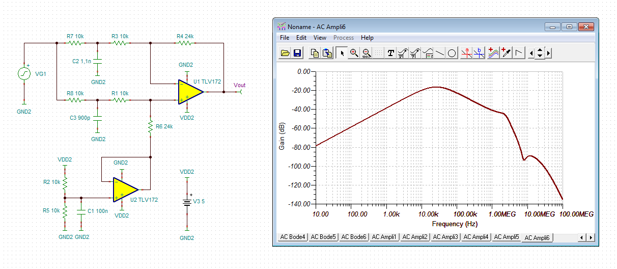
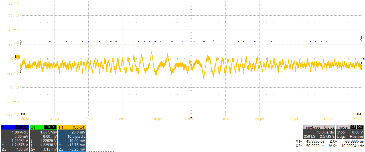
I also have up to 10mVpp of differential noise which gets as low as about 300kHz - this is getting into the original circuit's opamp output. The waveform below is measuring the differential output using the scope subtraction. Is this the expected behaviour of this IC or have I done something wrong? It's certainly well above any noise specs in the datasheet but they stop at 100kHz/200kHz. Should I be applying more low pass filter?

Thanks

Stewart

  • Hi Stewart,

    this could be an artefact of your scope measurement. Your scope might degrade the symmetry of AMC1300's output stage. I would connect the differential amplifier from figure 52 of datasheet to the output of AMC1300 and would measure the residual noise at the output of this differential amplifier. Note, that the circuit from figure 52 contains three filtering caps to provide adequate low pass filtering...

    Kai
  • Hi Kai

    I originally created a differential amplifier circuit then worked backwards to find the exact source of the noise. Here's the diff-amp circuit:

    I then also added a pair of 56R resistors to the output of the AMC1300B in case driving the capacitance of the track back to the diff-amp was causing a problem - though it's not really characteristic of a output drive stability problem. Here is the output of this diff-amp:

    Basically I want to know if this is the level and characteristic of noise I should be expecting (and I just need more low pass filtering or see if I can live with it) or if I'm doing something wrong in my circuit.

  • Hi Stewart,

    R12 = 10.98?

    Your filter looks good. But I would increase all the resistances a bit.

    Kai

  • Sorry that's a typo in the drawing R12 = 10.98k (actually 2x 5.49k).

    I was hoping someone else was running the same isolator and could quickly perform similar tests as me. For now I'll live with it and see how I go - probably some more low pass filtering.

  • It looks like the AMC1311EVC uses about 10k around its differential amplifier. I'll try something similar when I can.
  • Hi Stewart,

    when you have a look at your scope plots, you will notice some discrepancies. The first scope plot shows both outputs. The curves look very similar. When you subtract both curves with your eyes, you see that the difference is less than 10mVpp. But when you look at the second scope plot showing the scope subtraction the difference is up to 40mVpp. This looks a bit strange to me. That's why I said that the scope measurement might create some artefacts.

    Unfortunately, neither the datasheet nor the EVM user guide of AMC1300 recommend some concrete low pass filtering. And yes, the transmission from the input side over the isolation barrier is done using a modulation scheme which not only generates lots of ripple but also noise. So, as usual in such cases, you must find a compromise between the carrier ripple rejection (noise rejection) and the signal bandwidth. You cannot have both, zero ripple and infinite bandwidth. If a good ripple rejection is important for you, than choose a heavy low pass filtering, at the cost of signal bandwidth. But if you are interested in highest signal bandwidth, on the other side, then choose a less efficient low pass filtering and accept more ripple.

    Let me tell you how I see the situation: Figure 22 shows that the most linear range seems to reach to up to 100kHz. So, I would set the corner frequency of low pass filtering at less than 100kHz. Then, if necessary, I would decrease the corner frequency up to the point where the resisual ripple is acceptable for me.

    Also check the situation with a fresh AMC1300 to get a representative understanding of the AMC1300's behaviour.

    Kai
  • You're right Kai, I would expect noise from the SD modulation/demodulation. The subtraction oscillogram is probably also imperfect; I was mostly interested in the shape rather than the magnitude when I was tracking down the source of the noise (e.g. it's not being caused by other parts in my circuit).

    I understand what you mean with Figure 22. There is little to benefit from trying to amplify/keep the high frequencies beyond the bandwidth of the isolator itself. I'll do some tweaking to my filter - it should be OK anyway. I do want to keep a good bandwidth for digital/sampled current control.
  • Hi Stewart,

    I would use such a filter topology in the differential output amplifier:

    In this simulation ideal passive components are assumed. The peak of about -70dB at 3MHz comes form the finite common mode rejection of TLV712. This simulation underlines how important it is to use an OPAmp with a good CMRR (common mode rejection ratio). Another good idea is to have the low pass filtering outside of the feedback loop:

    And the following simulation shows how important it is to use passive components with very low manufacturing tolerances within the differential amplifier in order to not degrade the symmetry. 10% manufacturing tolerances are assumed for C2 and C3 and look how extremely the common mode rejection is degraded:

    Of course, you still can add small but identical caps in parallel to R4 and from the +input of U1 to signal ground. This will keep the phase margin high and improve the stability of differential amplifier.

    Kai