This thread has been locked.

If you have a related question, please click the "Ask a related question" button in the top right corner. The newly created question will be automatically linked to this question.

INA226: INA226 - ADC Resolution Spec Req

Part Number: INA226
Other Parts Discussed in Thread: , INA233

Hello,

I am planning to use INA226 in my module design to measure voltage and power through sense resistor. In Datasheet 1 LSB step size for shunt voltage measurement is given as 2.5 uV and ADC native resolution as 16 bits. Can i get a detailed specification of ADC so that it will be ease for me to proceed my design.

1) What is the ADC reference voltage ?

2) What is ADC offset error ?

3) How reference voltage is generated If reference voltage is generated from power supply source then should i need to add and filter circuit so that my reference voltage is pure.

  • Hello Rohith,


    Welcome to the E2E Amplifiers forum.


    1. I do not know what this ADC reference voltage is. It is set internally in the device and cannot be adjusted. It is most likely Vs/2, but knowing the reference voltage is not critical to use of INA226 or most of our digital current/power monitors. The INA226 will always sense the differential shunt voltage (Vsense) regardless of what the common-mode voltage (VCM). Of course the device only operates within spec for a VCM range of 0V to 36V.


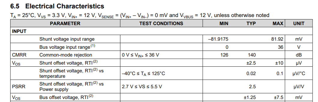
    2. The ADC offset error is simply the input offsets we specify for the shunt and bus voltage measurements (see below a picture from the datasheet). So the ADC offset when measuring shunt voltages is maximum ±10µV (or 4 LSB) and offset when measuring bus voltages is maximum ±7.5mV (or 6 LSB).


    3. If you wish to ensure the ADC (thus INA226) works to its best performance then you will want to follow the simple Layout guidelines example in datasheet section 10. As for all amplifiers using a decoupling bypass capacitor of 0.1µF will ensure a stable power rail internally in the device. The capacitors should be placed as close as possible to the VS pin.

    Hope this helps.
    Peter Iliya

  • Dear Peter,

    Thanks for your instant reply I am planning to use INA226 for 12 A current measurement with 1mohm resistor when i simulated rms error available in TI product page it shows 4% error at current range less than 4 A. Can you please ellaborate this issue. Is there any better part available for high current measurement.

  • Hey Rohith,

    You're absolutely welcome.

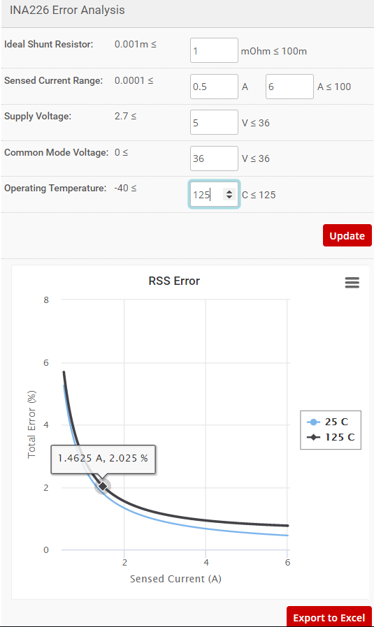
    That simply cannot be correct. Here is the same tool and assuming 1 mOhm shunt resistor and worst-case environment: VCM=36V and 125C. Even with the stressing factors, the RSS error at 1.46A is <2.03%. At 4A, RSS error < 1%.

    When current is 4A and shunt it 1mOhm, the sense voltage is 4mV and this is much greater than the device's input offset. Are you running the error calculator similar to me or with other conditions?

    Best,

    Peter

  • Dear Peter,

    This was the tool which i was simulating , but I used 0.6 mohm resistor initially in my design now i have changed 0.6 mohm to 1 mohm.

    Is there any equivalent part with better accuracy for low current measurement. If you see in the above error computation tool for current less than 0.5 A error rate is 4%.

    I am planned to use the same INA226 for 12A, 4A and 0.75 A current. I also planned to use the same 1mohm sense resistor for all current measurement.

    Shall i use INA226EVM design as reference for my circuit.

    Also in INA226EVM user manual it is mentioned that SM-USB-DIG connector is 10-pin connector socket but in user manual BOM this part number is mentioned ( 851-93-10-20-001000 ) which is 50 Position Receptacle Connector 0.050" (1.27mm) Through Hole, Right Angle Gold.

    Kindly confirm the SM-USB-DIG connector part used in INA226EVM module. I have plan to purchase EVM also for my design verification.
  • Dear Peter,

    It will be useful if you clarify my following query,

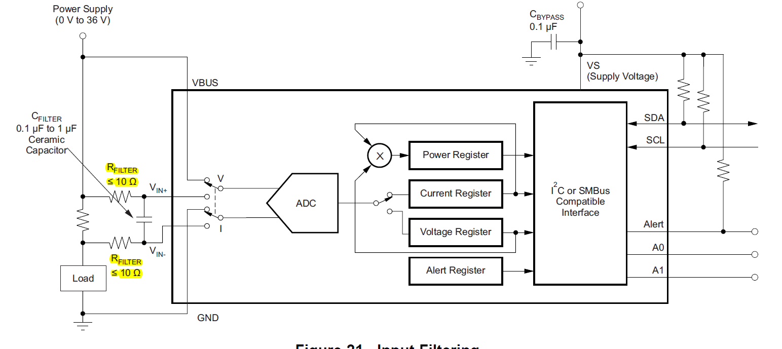
    As per INA226 datasheet it was recommended to add Filter circuit across V sense pins. Since i am using 1mohm sense resistor for voltage sense what resistor should i use for R filter shall i use same 1mohm resistor for filtering purpose.

    If i use 10 ohm resistor will the voltage drop affects my resolution of current measurement. Also i will be happy if you provide input impedance of ADC front end so that series resistor what is use for filter circuit will not load my Vbus line.

  • Hey Rohith,


    When thinking about error, you need to consider it in terms of shunt voltage (Vshunt) and input offset voltage (Vos). Additionally, you need to understand what the minimum and maximum currents you want to sense. You will most always have the greatest error at the minimum sense current because offset error will begin to dominate. Error% = 100*Vos/Vshunt

    1. What is the minimum current you want to sense and at what error?
    2. What is the largest current you need to sense?
    3. What is maximum allowable shunt voltage your system can tolerate?

    The questions above all relate to each other and it's hard to propose a solution without knowing all of these bounding factors.
    If you want better accuracy at lower current, then you could choose a larger shunt resistor. Although, this will increase your shunt power dissipation at higher currents and you need to ensure that Vshunt <= 81.92mV when ILOAD= max current because this is maximum voltage INA226 can measure.

    The INA226 and INA233 are the most accurate digital current shunt monitors with 10uV max input offset, so your only option is to increase shunt resistance or employ a calibration procedure where you make a measurement of a known current, record the measurement, and then subtract this offset from all your other measurements.

    For the EVM, the 50 pin connector (J1) is what the SM-USB-DIG physically connects to and this interface card is included in the INA226EVM Kit. You can view the evm kit contents in section 1.1 of EVM User's Guide.

    ---
    Why do you want to filter the input shunt voltage? Is your sense current noisy? The datasheet only recommends this filter is the current is noisy, current contains harmonic transients at 500kHz or harmonics of this, or there are very fast voltage transients at the input that could damage internal ESD cells. Even if the current is noisy, you can increase the conversion time or also the number of averages the INA226 measures. These values are programmed by user into INA226. See section 7.4.2.

    If you must need the input filter, then the value of the input resistors (R10 and R11) do not matter as long as they are less than 10-Ohms. We do not have input impedance for ADC, but it will not load your VBUS line. The input bias current (IB) is limited to 10uA per input pin. You are dealing with amps of current so it will not load down your bus.

    The input impedance of the VBUS pin is 830 kOhm as shown in datasheet Electrical Characteristics table. Thus, the resistor divider (R125, R13i, and R14i) will actually load down this 830 kOhm internal impedance. So ideally the VBUS node should equal 400V*(4.75/(300+4.75)) = 6.2346V, but VBUS will actually equal 400V*(Rx/(300+Rx)) = 6.1996V, where Rx = 830||4.75.


    Hope this helps.
    Peter

  • Dear Peter,

    Thanks a lot for your valuable suggestion.

    Regards,

    Rohith K