This thread has been locked.

If you have a related question, please click the "Ask a related question" button in the top right corner. The newly created question will be automatically linked to this question.

INA300: SCH Review: Vpwr = 5V; Itrip = 10mA; I_Max = 100mA

Part Number: INA300


Hi Sir,

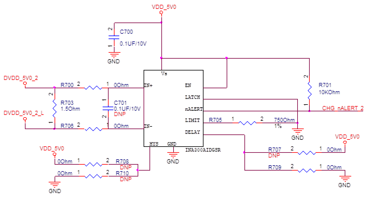
Could you help to check below SCH? Please help to provide your suggestion, if there is any concern. Thanks.

Vpwr = 5V

Itrip = 10mA

I_Max = 100mA

  • Hello Teresa,

    Functionally speaking this schematic looks good and will satisfy the listed system requirements. I will note that designer should make sure that this schematic will satisfy their error requirement. Given R705 is 1% and that ILIMIT_minimum = 19.9uA, VLIMIT_minimum could possibly become 14.775mV, which means Alert pin would trip at 14.775mV/1.5Ohm = 9.85mA. This equates to a -1.5% error in trip current.

    This is just something for customer to consider, otherwise everything looks good. Max shunt voltage is 150mV and within the input's full-scale range of 250mV. R703 will need a power rating of at least R*I^2 = 1.5*0.1^2 = 15mW.

    Delay is set for 50us and device is configured for transparent mode (LATCH = low). Hysteresis is floating so it is set to 2mV.

    Hope this helps.

    Best,
    Peter
  • Hi,

    Peter thanks for your information.

    Customer meets a Vdrop problem on the 1.5 ohm application.
    For ITrip is 10mA and IMax = 100mA, do you have any recommend minimum value of the Rshunt?
    If they used 250m ohm, what's the error% on the Vtrip?
  • Hey Teresa,

    You're welcome.

    The recommend minimum value of Rshunt is completely dependent upon what customer error budget is. In order to calculate error, customer needs to calculate what the maximum possible input offset voltage is given their system parameters: VCM, VS, temperature change from 25C. It is a fairly straight-forward and easy exercise. Please direct customer to our Current Sensing Video training or one basic circuit cookbook example showing how to calculate maximum total error.

    http://www.ti.com/lit/an/sboa336/sboa336.pdf

    There is also overlap in error analysis between current sense amplifier and operational amplifiers. The TI Precision Labs covers this material as well:

    Offset error will dominate for the lowest current that needs to be measured. Once shunt voltage becomes larger, then gain error will dominate.

    Given 250mOhm shunt and 10mA minimum current, this yields 2.5mV Vshunt_min. With delay set to 50us, the Vos_max = 500uV. However, this Vos is when VS=3.3V and Vin+ = 12V.

    Vos_CMR_max = |12V - 5V|*10^(-100dB/20) = 70uV (over -40C to +125C)

    Vos_PSR_max = |3.3V-5V|*150uV/V = 255uV (over -40C to +125C)

    Vos_total = Vos_max + Vos_CMR_max + Vos_PSR_max = 825uV.

    Thus, once Vshunt = 2.5mV, the maximum possible error is 100*(825uV/2.5mV) = 33%. Note this error does not include the offset voltage drift as I do not know what customer's temperature range is. When using the maximum and minimum error specs, you are calculating the worst-case error.

    Best,

    Peter

  • Hi Peter,

    Thanks for your sharing and instruction.