This thread has been locked.

If you have a related question, please click the "Ask a related question" button in the top right corner. The newly created question will be automatically linked to this question.

THS7372: could we provide THS7372’s S parameter or IBIS to customer?

Part Number: THS7372


Dear Team:

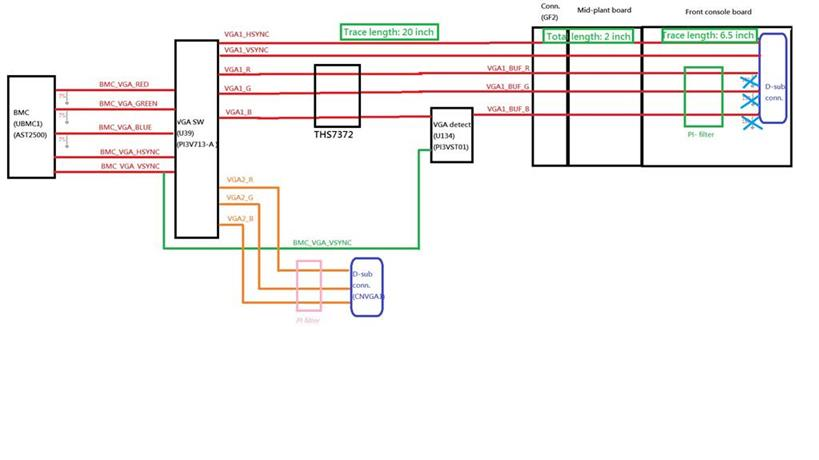
Due to VGA topology is complicated and VGA transmission line is too long, so we would like to do the VGA signal integrity simulation, Could we provide the THS7372’s simulation model?

Or , could we provide THS7372’s S parameter or IBIS to customer?


  • Hi Thomas,

    We don't have any of those models for this device. Each of those models give different parameters for the part. What specifically are you looking to learn about that part?

    Thanks!
    -Karan
  • Dear Team:

     I got customer feedback.

    I think we can use 1080P60, 30 inches PCB loss to calculate.

    =====

    Hi Thomas(TI),

    Per our talk, what can do to make sure the risk  for rise/fall time ,overshoot/Undershoot and Skew?


  • Dear Team,
    any updated?
  • Hi Thomas,

    The datasheet lists the input impedance of the amplifier as 800kOhms || 2pF. So they can test their impedance matching circuit with this. If the transmission line is properly terminated with an impedance matching circuit, there should be no problems. This is what the TINA model would have at its input anyways. As for rise/fall times, the TINA model just simulates what is there in the datasheet. Overshoot/Undershoot should also be minimal with a properly matched transmission line. And lastly, unless their signal is already skewed, the skew from the device should again be what is listed in the datasheet.

    Thanks!
    -Karan
  • Hi Karan,
    what's the TINA model ? And how mothed can we do to make sure the impedance matching ? Due to via and connecter will factor cause mis-match, and we can't to aviod it in our system design. Can you proivde the mothed to me that it can guarantee design risk is low in this topology?
  • Hi Sally,

    A TINA model is a SPICE based model we provide with some of our parts.

    When there is a long transmission line, longer than a quarter wavelength, there are reflections on the line. VGA transmission lines are typically impedance matched at both ends to look like 75 Ohms to avoid these reflections. As you mentioned via and connectors can cause mismatch and for this reason I have attached some high speed PCB layout techniques to help you design your board.

    High Speed PCB Layout Techniques.pdf

    Thanks!

    -Karan